Showing posts with label repair. Show all posts

Monday, January 16, 2012

Toshiba 50HP66 50" plasma, loud pop, screen went dim - what to do


Question: 
A friend of mine recommended you. i just bought a toshiba 50hp66 50" plasma. loud pop, screen went black. after sitting off for an hour turned it back on. everything works but is very light colored and dim. pictures seems to be clear, no lines,spots etc... not sure which board would cause a dim screen. thanks in advance.  Travis

Answer:
This is a known issue with Toshiba 50HP66 and a bunch of other TVs using the same display and supporting boards.
(in a plasma TV almost everything is about the display being used; same display in two different models means that bunch of other boards are also the same, namely the sustain boards, the buffer board(s) and the plasma display controller; the main board is different for different OEMs and that's about it. Oh well, the power board may also differ, but the differences would be very minimal, e.g. an extra 15V power needed by the main board).

Anyway, what goes bad with a pop is one of the sustain boards. Sometimes both, but most commonly just one of them at a time.

Here is how the TV looks at the back when you open it (click to get larger picture):
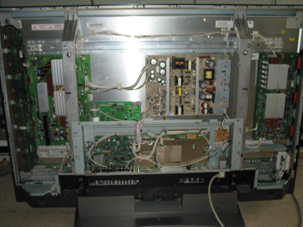
What usually goes bad is either the larger board with three heat sinks to the left of the TV (called YSUS board , or, sometimes Y-Main) or the one with two heat sinks at the right side of the TV (called ZSUS or sometimes X sustain).

Sometimes, but relatively rarely, it is the large board in the middle of the picture (and the TV) that goes bad  - that's the power board; if the TV is completely dead and has no front LED indication, no response to power button then the first thing to check is the power board.

Anyway, in your case it is mostly sure that it is either the YSUS or the ZSUS board that is bad.

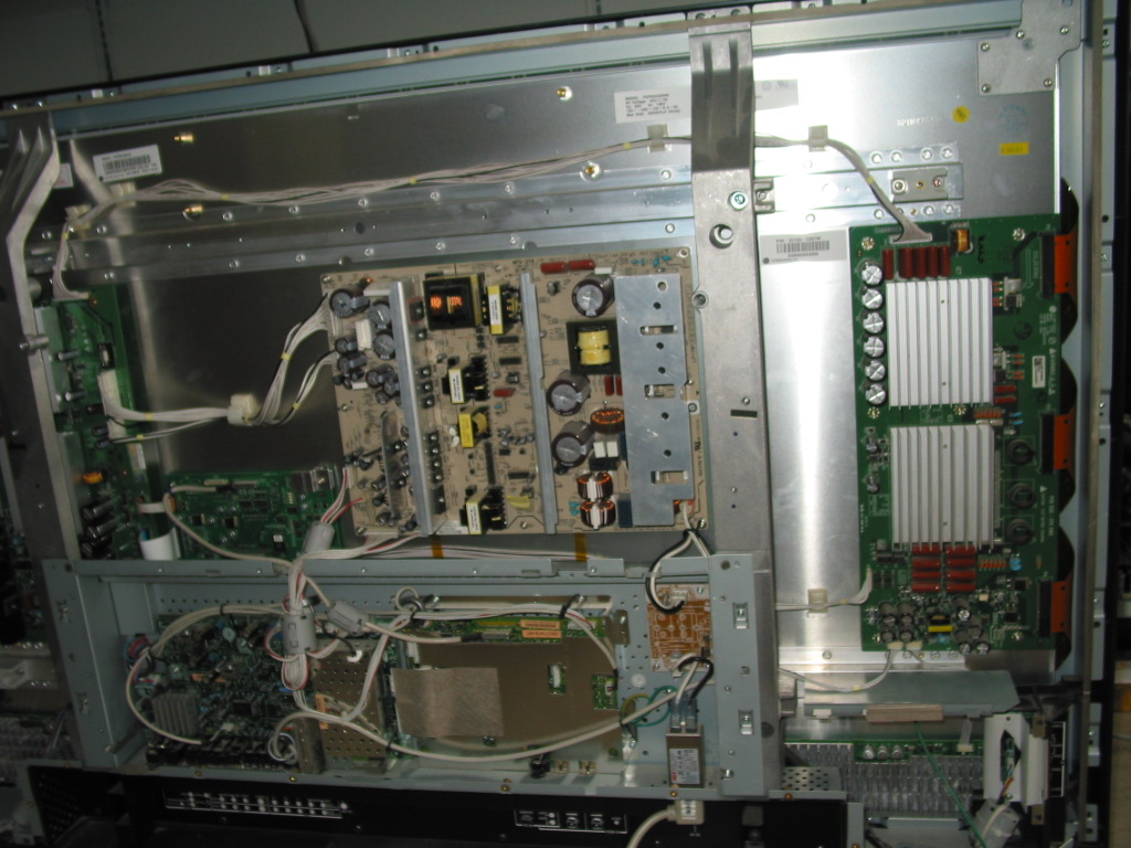
And since you say you do have a faint, dark image on the display then it is most likely that it is the ZSUS board that has failed.

Here's a closer look at it:
Now, customers often ask how to make sure the board is bad before sending it.

They read around Internet and search for swollen capacitors , burn marks and other signs of a failure.

Well in case of those boards the truth is you don't normally see signs of a failure.

What fails is under the heat sink and above the board. There's simply no way for you to see it there, but for your eyes only I've blogged about the subject before so you can actually see what has happened there if you're curious:

http://blog.coppelltvrepair.com/2010/02/y-sustain-6870qyc004b-6871qyh039a.html

Sometimes the failure results in a short and that can be measured , but often times (as in your case) it results in an open circuit and that just can't be measured without applying power.

Which means the easiest way to test the board is to put it in a working TV to see if it will still be working.

And that's exactly what we do when we receive one of those for service.

If interested in using our service or servicing it yourself...here's a link for  you:

Toshiba 50HP66 repairs and modules from Coppell TV Repair

Monday, July 25, 2011

PHILIPS 37PF9431D dead, power board 310432838621 not producing output voltage

Coppell TV Repair for long offers a repair service for the above mentioned power board, but today I've got a board with a problem that I have not seen before so I decided to share it so that those blog followers who wouldn't anyway pay for a service at least get a chance of doing it right by themselves :-)


Symptom: When connected to power, the board clicks periodically about once every second - not a relay click, but an electric click as of a toroid on overdrive only more quite and nicer. Like it's trying to start and failing.

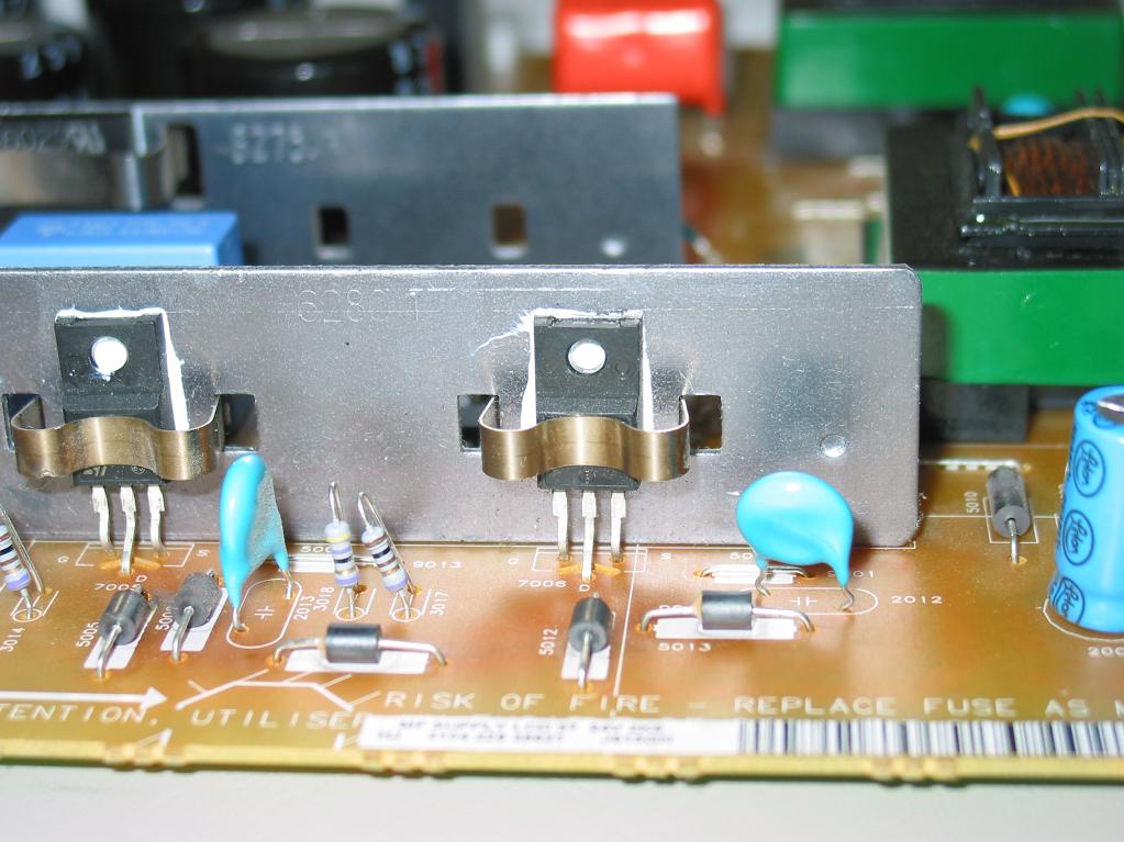
Problem: it turned out transistor 7006 had failed. Drain-Source was shorted and so the transistor had to be replaced. This is the beast in reference:


It is STP15NK50ZFP SuperMESH MOSFET  - 500V / 14A - and since we couldn't find one handy we used a substitute replacement.

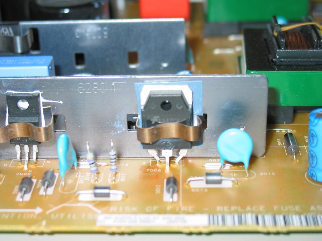
Here is how it looked after the replacement:

Note the insulation barrier behind the replacement - if you do something like that you will need to have one too since the original is in plastic TO-220 corpus whereas the replacement is in TO-247 has metal back electrically connected to the drain (or source, whatever).

We checked for other damages on the board and when we couldn't find any we connected to power and voila, it worked like a charm!

If you happen to have the same problem and can't find the appropriate replacement, below is a chance to get what we used at what we call reasonable price (especially considering you've got the whole solution laid in front of you):


Thursday, December 9, 2010

MLT166A POWER BOARD TEST AND REPAIR - AKAI LCT2701AD and LCT2701TD

A company has sent us a bunch of those boards to repair and we are sharing some of our expertise on how to test and repair them.

Those supplies are used in AKAI LCT2701AD and AKAI LCT2701TD models.


(If you need Coppell TV Repair to repair your power board please first make sure it needs repair as per the below instructions and then contact us to arrange repair. From what we learned odds are good it may indeed be faulty.)


Indeed, this is apparently a poorly made power board because all of the ones that we received had been previously serviced already.

So how do you know if it works?

TESTING POWER BOARD MLT166A
When connected to 110V AC through the main connector CON0 (at the lower right corner on the picture) the board is only supposed to produce 5V standby voltage. This shows up on connector CON2 which is the second white connector from the top on the left side of the board. It is between the two heat sinks and next to the order of three capacitors EC18, EC19 and EC20.

When testing the board we recommend that you disconnect all load from it, i.e. unplug all connectors except the one that feeds AC power in.

The CON2 connector has 6 pins organized in three groups of two pins like this (starting from the top):

* STB (aka PS_ON)
* STB
* GND
* GND
* +5V STB
* +5V STB

The lowest two pins is where you get the standby 5V power. You will need a digital multimeter to measure them. It is OK if reading is 10% off, i. e. anything between 4.5 and 5.5 V will do as long as it is stable.
To measure the voltage you connect one probe to either of the +5V STB pins and the other to either of the GND pins.

To activate the power supply (which is what happens when you pres the POWER ON button on your TV) you need to pass the 5V to any of the two STB pins.
We do that by simply soldering a resistor of about 100 Ohm between the two opposite pins of CON2, but you can as well just short them - in this particular case.

Once you do, the board should start making a humming noise and the rest of the voltages should show up:

CON1 has 3 sections - 3 pins for +12V, 3 pins for GROUND and the rest for +5V:
* +12V
* +12V
* +12V
* GND
* GND
* GND
* +5V
....

CON3 and CON4 each have half of their pins for GND and other half for +24V needed for the inverter boards.

If you get all those voltages then your power board does not need a serious servicing.

COMMON PROBLEMS WITH MLT166A

1) Probably the single most common problem with those boards are bad electrolytic capacitors. You should check and replace those regardless of whether the above test passes or fails. Bad capacitors can change board's behavior under load and can render it useless even if it passes the simple no-load test.


Electrolytic capacitors are the cylinders with shiny tops that can be seen all over the board.

Bad ones can usually be spotted by their bulged tops compared to the other, normally flat ones.


Behind the above mentioned connector CN2, for example, is a trio of capacitors that had to be replaced (or was already replaced) on any single board that we've seen. Those are EC18, EC19 and EC20.
Originally they are rated 1000 uF / 10V each.
If you need to replace them, you should replace them with 105 degrees , 1000 uF or slightly more and at least 10V rated capacitors - the higher voltage, the better (bear in mind they get larger though).

Since EC18 and EC19 work in parallel it is also completely acceptable to replace both of them with a single 2200 uF / 25V capacitor that will work better and last longer.

One one of the boards we serviced we've also had EC11 apparently bulged so we had to replace it as well.

On your board you may have yet a different one that needs to be replaced.

If you need parts, let us know and we can sell and send them to you!

2) The 5V output on CN1 (the lowest 5 pins of the connector) provides power to all the logic functions needed when the TV is working. They flow through a power transistor located at the back of the board which carries both filter and control function.

Simply said, think of it as an operating switch which has 3 connectors - input, output and a controlling (gate) connector which tells it when to activate.

That transistor is apparently badly rated because on many of the boards we received it was bypassed by simply shorting the input and output and completely ignoring the switch control input:


While rude, this solution is a cheap and efficient one if you don't see the 5V at the connector of your board , but you see them on CN2.

If both of those fail to help you, we'll be glad to try our luck diagnosing and fixing your board for $50 or so.
Just send it over!

Thursday, September 16, 2010

How to test power supply R0804-0901 from Polaroid FLM-3232 / Polaroid FLM-323B

Since we repair those power supplies (contact us for repair if you need yours repaired!) I am often asked how can it be tested if it works.

"My Polaroid just died and after some research I found that it's usually the power supply and then I found your blog and learned that CoppellTVRepair repairs it. I opened up the TV, looked at the board and I indeed have R0804-0901. There are no swollen caps or broken elements that I see...I want to use your service, but I want to know I actually need it before I pay."

That's a fair statement. To start with, only about half the time it's the power supply that goes bad. The other half it's the main board and , at least for the time being, we can't help with that...with more than the helpful information I already posted a while ago about cross-referencing main boards from Polaroid and Memorex.

So it makes a lot of sense to test the power board instead of assuming it is dead.

And here is how:

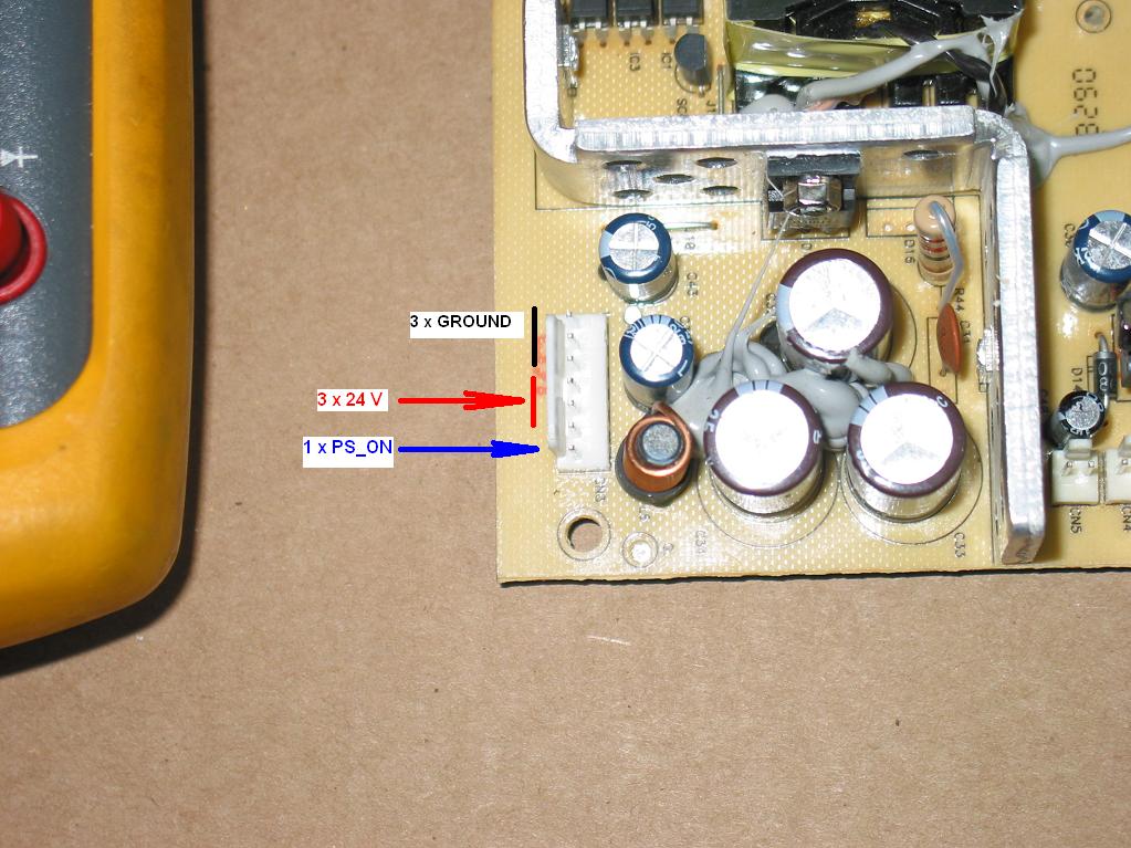
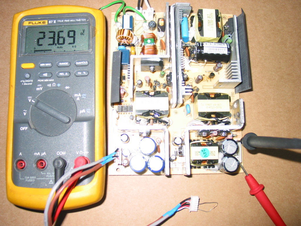
The R0804-0901 is extremely simple in regards to operation and outputs. Unlike most TV power supplies its only standby circuit produces 24V and those can be measured at any time - on or off - at connector CN3, where the first three pins are ground, the second three are +24V and the last one is used to turn on the secondary power source for the back lights:


I measure the voltage by simply feeding power to the supply and sticking the meter probes in the connector:

Most of the time, if you have 24 volts there, your power supply is good.

Now if you want to be sure that everything works, then you also need to test the secondary output, which is at connector CN2 across the board.
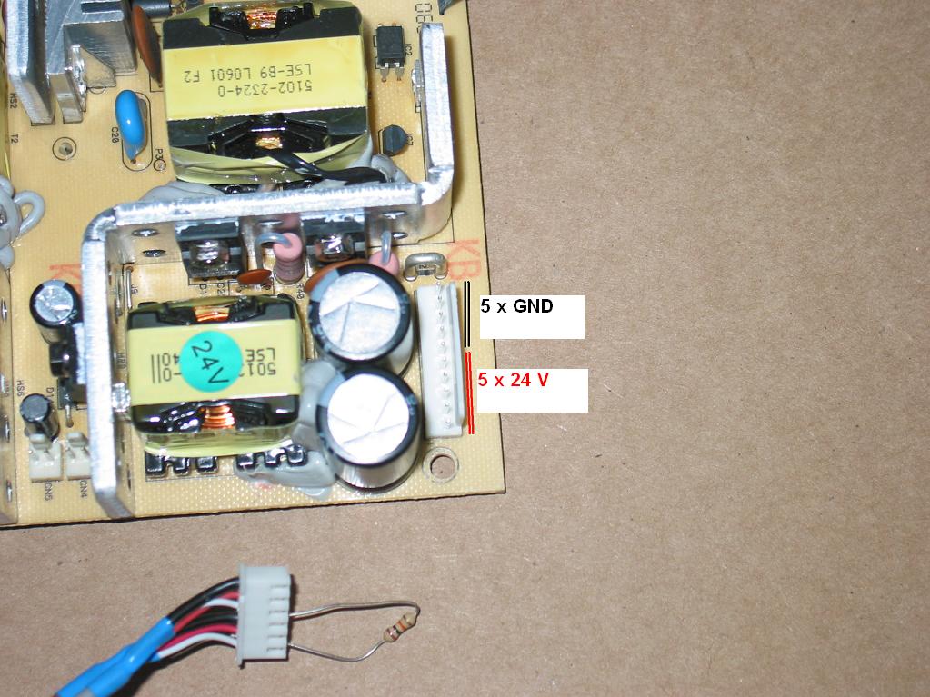
It is even simpler as it has 5 pins ground and 5 pins 24 volts (separate from the first ones!):

In order to do that, though, you need to turn that circuit on, which is done by connecting the PS_ON pin on the first connector (look above) to the primary +24V through a resistor. 
Anywhere 1 kOhm to 10 kOhm should do.

On the picture below I had used a simple cable from another TV to allow me to easily connect the lowest pin to some of the ones above it through a resistor.
You will likely not have such a cable handy...but then again you only care about this test if your TV powers on and off, has sound, but there is no back light.

Monday, September 13, 2010

Samsung LN-S4041D LNS4041D shuts down intermittently

Well I'm back from Europe and overloaded with work!

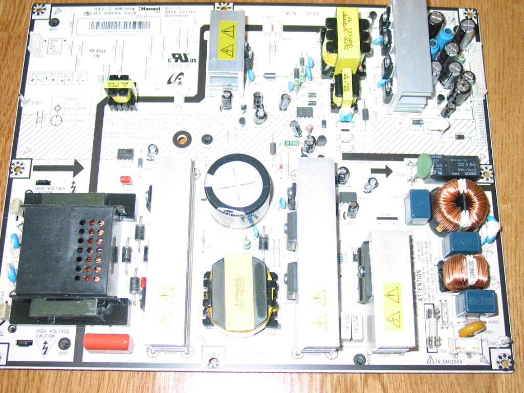
This post is for a trivial problem with the BN44-00134A power supply used in some Samsung LCD TVs.

Just yesterday came across a LN-S4041D TV unit. It was brought in for service with complains for intermittent shutdowns after working for a while.

Sounds familiar - many TVs would do that, very often due to puffed capacitors in their power supply boards.
(of course it is not always the case; remember, nothing is ever certain, so the next time you call a service technician please spare their day and tell them the problem you see and not what you think is causing it!)

So anyway, after taking the back off and looking at the power board this is what I saw:


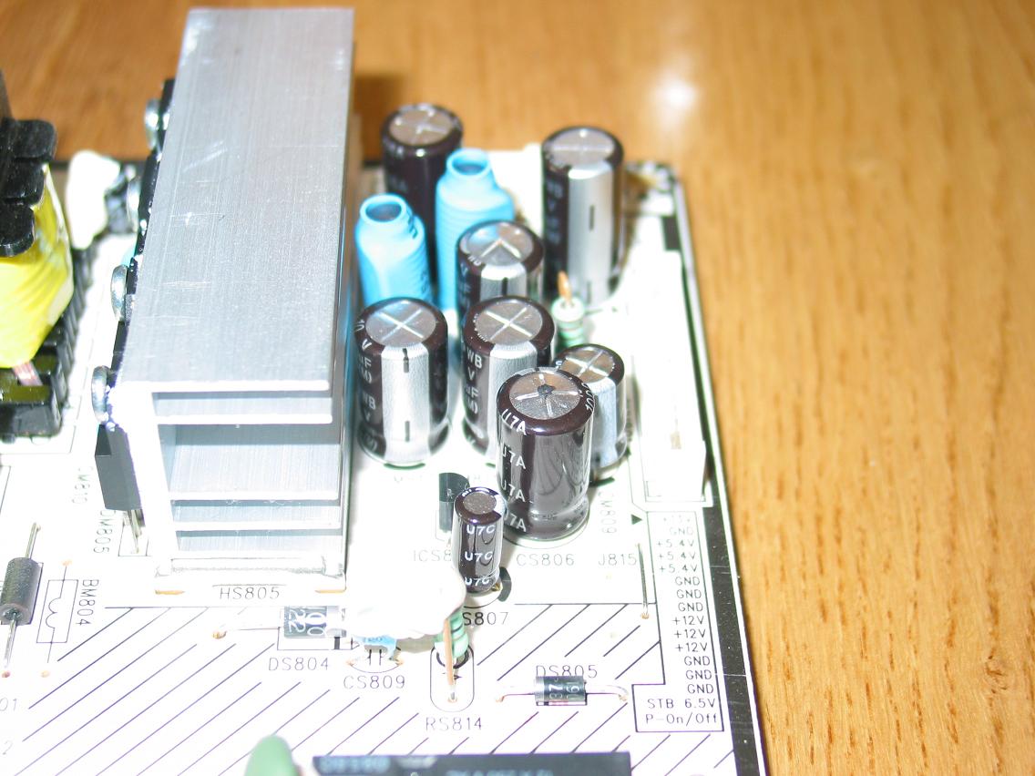
An even closer look at the upper right corner revealed the following:

Did you notice the two puffed caps? They are a little harder to see on the image - I am an electronics and software engineer, after all, not a photographer - but if you know they are there you will see them even on this image.

Puffed caps like that are usually connected in parallel and usually have the same value.

In this case they were both 1000 uF / 10V .

When replacing puffed caps it is usually best to use the same value for their capacity (1000 uF in this case) and always safer to use same or, better yet, higher value for their rated voltage.

Another important property of the electrolytic capacitors is the upper temperature range they can work on. On most boards these days this is 105 degrees Celsius and I recommend using the same or higher value.

Replacing those two with a pair of 1000 uF / 16V / 105 degrees fixes the set and will keep it running for a long long time.

Maybe happily ever after.

Friday, February 26, 2010

Polaroid TDA-03211C red light, does not power on

A few days ago receive a Polaroid TDA-03211C which was powering on to red light, but refused to continue past that.no matter what.


The power board had the main capacitor of the SMPS visually swollen and I decided to replace it, but that didn't help. It looked the power was just fine and I could measure its output.

That left the main board 200-107-GT32XA-AH REV:A as the only component to blame.

After examining the board I found nothing to suggest where the problem might be and without a schematic I would better check for replacements before starting to debug.

Well all 200-107-GT32XA-AH version on Internet had been recently sold!

eBay, ShopJimmy, Discount-Merchant - nobody had it , although reportedly all of them had it at some point, some actually rather recently.

However, I realized there was another board in circulation, the 200-107-GT321XA-BH one.

At the time of writing this it is still available for $125 on eBay from several vendors.

In my opinion, $125 for a replacement board for a 32'' TV is too expensive, but I was lucky to be able to find one vendor who was selling it at a reasonable price and I decided to bite the bullet and try it.

Long story short, it worked and the TV is now just fine.

Another happy customer.

I'd like to think the problem with the board is something minor rather than overheating and disconnection of SMD processor. If you ever find out what is going bad on that board please post it here.

Tuesday, February 16, 2010

Sony KLV-40U100M problem - dead, no picture, no sound, no power - 715T1723-J

A Sony KLV-400U100M LCD arrived in shop today with no signs of life - no LED on front panel and no response to any of the buttons whatsoever. Comletely dead.

One could hear a short buzz when plugging in outlet, though, so at least power board was showing some signs of life.

So it was either power board or main board.

Power board 715T1756-F was a bit difficult to understand without a schematic as it doesn't have any indication of what it should provide, but by looking at the back of board where the connector contacts were I was able to isolate the standby power which turned out to be 5V and available.

With a little guessing I could also figure the power on signal pin and upon signalling it with 5V through resistor I was able to bring up other voltages.

That ruled out the power board as a suspect and left the main board 715T1723-J as the prime suspect.


And indeed it was!

I'll eventually blog about what I learned as it will sure help some, but for the time being I have to go....sorry.


In the meantime, if you need your own board serviced feel free to contact me.

Saturday, February 13, 2010

HP PL5060N problem - 6870QZC004A / 6870QYC004B / 6871QZH044A

There's a problem I do not remember seeing before, so I decided to note it here.

A 50'' plasma HP PL5060N has come in for repair with typical sustain problem - burned fuse, power with no image.

Turned out it was the Z sustain and after replacing the two IPMs YPPD-J015B and YPPD-J016B with new modules and doing some quick tests I plugged the board back in, replaced the fuse and turned on the TV.

The TV showed up the HP logo for a few seconds, then turned black and restarted itself.

At first I thought the problem was in the main board or the power board, since I got good image on screen if only for a few seconds, suggesting sustains were normally functional.

But I had a spare Z sustain board and for my luck decided to see if it will make the TV behave differently.

Surprisingly, it worked out well with it, something I frankly did not expect. I am glad I tried, because I would have sworn the problem was in either main board or power board.

Anyway, after further investigation it turned out that there were two problems on that ZSus board:

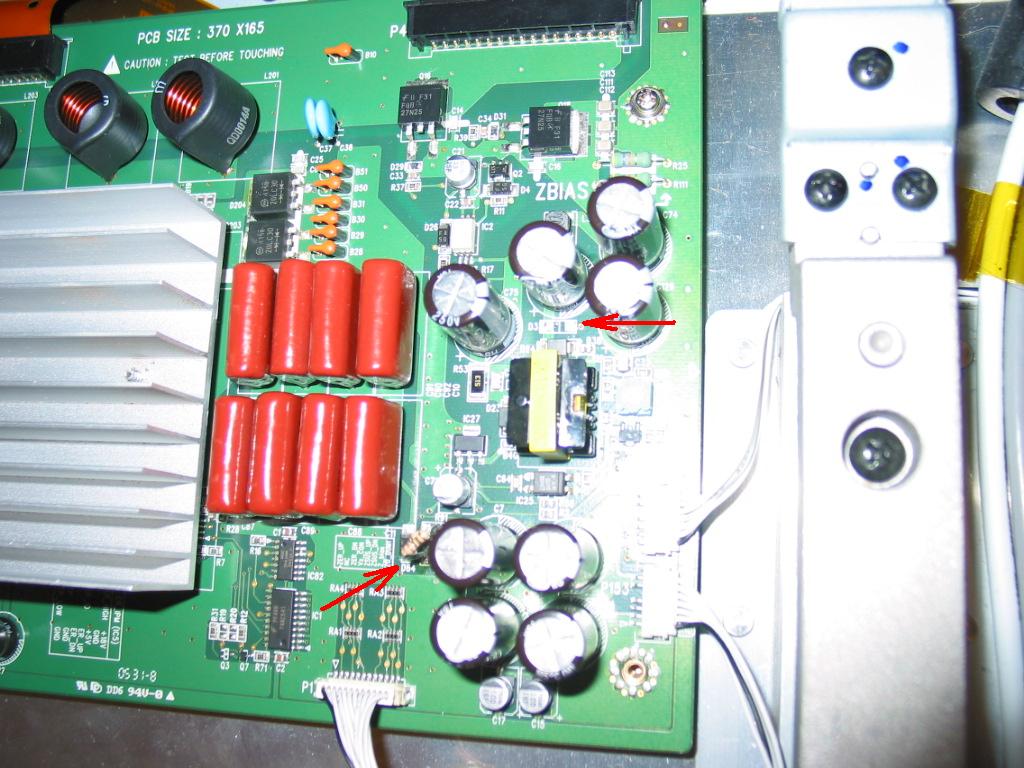
The R9/R91 resistors were both burned and the D3 diode was shorted.

The picture below indicates the component locations:


The R9/R91 are connected in parallel for a resulting resistance of 5 Ohm. I didn't have SMD resistors like them handy, of course, so I just replaced them with generic 0.125W pair of 10 Ohm resistors connected in parallel.

D3 is apparently a protection diode. It was completely missing in the 6870QYC004B version of the board that I had and which was functional. Call me what you like, but I had decided to leave it missing in the 6870QZC004A version as well.

After fixing R9/R91 and removing D3 the board allowed the TV to continue beyond the HP logo.

If you want YPPD-J015C or YPPD-J016C for your own DIY project or if you want your Z-Sustain or Y-Sustain repaired check out my store.