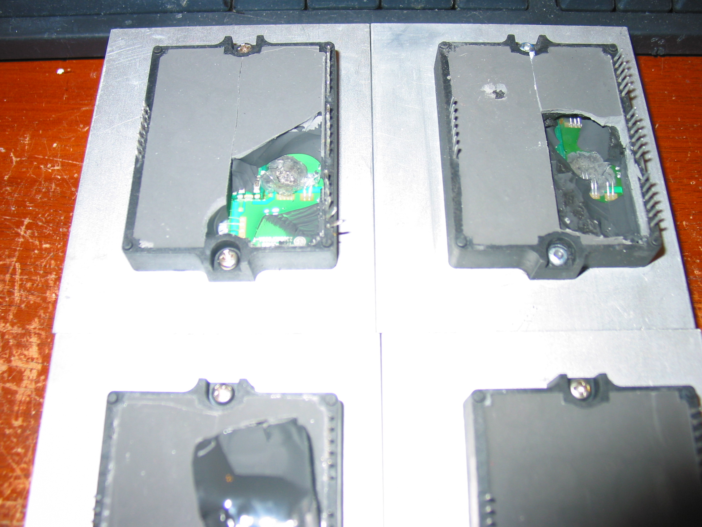
A company has sent us a bunch of those boards to repair and we are sharing some of our expertise on how to test and repair them.
Those supplies are used in AKAI LCT2701AD and AKAI LCT2701TD models.
(If you need Coppell TV Repair to repair your power board please first make sure it needs repair as per the below instructions and then contact us to arrange repair. From what we learned odds are good it may indeed be faulty.)
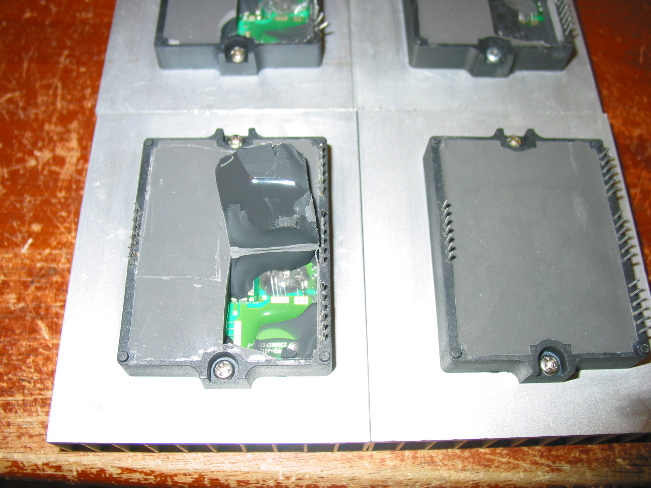
Indeed, this is apparently a poorly made power board because all of the ones that we received had been previously serviced already.
So how do you know if it works?
TESTING POWER BOARD MLT166A
When connected to 110V AC through the main connector CON0 (at the lower right corner on the picture) the board is only supposed to produce 5V standby voltage. This shows up on connector CON2 which is the second white connector from the top on the left side of the board. It is between the two heat sinks and next to the order of three capacitors EC18, EC19 and EC20.
When testing the board we recommend that you disconnect all load from it, i.e. unplug all connectors except the one that feeds AC power in.
The CON2 connector has 6 pins organized in three groups of two pins like this (starting from the top):
* STB (aka PS_ON)
* STB
* GND
* GND
* +5V STB
* +5V STB
The lowest two pins is where you get the standby 5V power. You will need a digital multimeter to measure them. It is OK if reading is 10% off, i. e. anything between 4.5 and 5.5 V will do as long as it is stable.
To measure the voltage you connect one probe to either of the +5V STB pins and the other to either of the GND pins.
To activate the power supply (which is what happens when you pres the POWER ON button on your TV) you need to pass the 5V to any of the two STB pins.
We do that by simply soldering a resistor of about 100 Ohm between the two opposite pins of CON2, but you can as well just short them - in this particular case.
Once you do, the board should start making a humming noise and the rest of the voltages should show up:
CON1 has 3 sections - 3 pins for +12V, 3 pins for GROUND and the rest for +5V:
* +12V
* +12V
* +12V
* GND
* GND
* GND
* +5V
....
CON3 and CON4 each have half of their pins for GND and other half for +24V needed for the inverter boards.
If you get all those voltages then your power board does not need a serious servicing.
COMMON PROBLEMS WITH MLT166A
1) Probably the single most common problem with those boards are bad electrolytic capacitors. You should check and replace those regardless of whether the above test passes or fails. Bad capacitors can change board's behavior under load and can render it useless even if it passes the simple no-load test.
Electrolytic capacitors are the cylinders with shiny tops that can be seen all over the board.
Bad ones can usually be spotted by their bulged tops compared to the other, normally flat ones.
Behind the above mentioned connector CN2, for example, is a trio of capacitors that had to be replaced (or was already replaced) on any single board that we've seen. Those are EC18, EC19 and EC20.
Originally they are rated 1000 uF / 10V each.
If you need to replace them, you should replace them with 105 degrees , 1000 uF or slightly more and at least 10V rated capacitors - the higher voltage, the better (bear in mind they get larger though).
Since EC18 and EC19 work in parallel it is also completely acceptable to replace both of them with a single 2200 uF / 25V capacitor that will work better and last longer.
One one of the boards we serviced we've also had EC11 apparently bulged so we had to replace it as well.
On your board you may have yet a different one that needs to be replaced.
If you need parts, let us know and we can sell and send them to you!
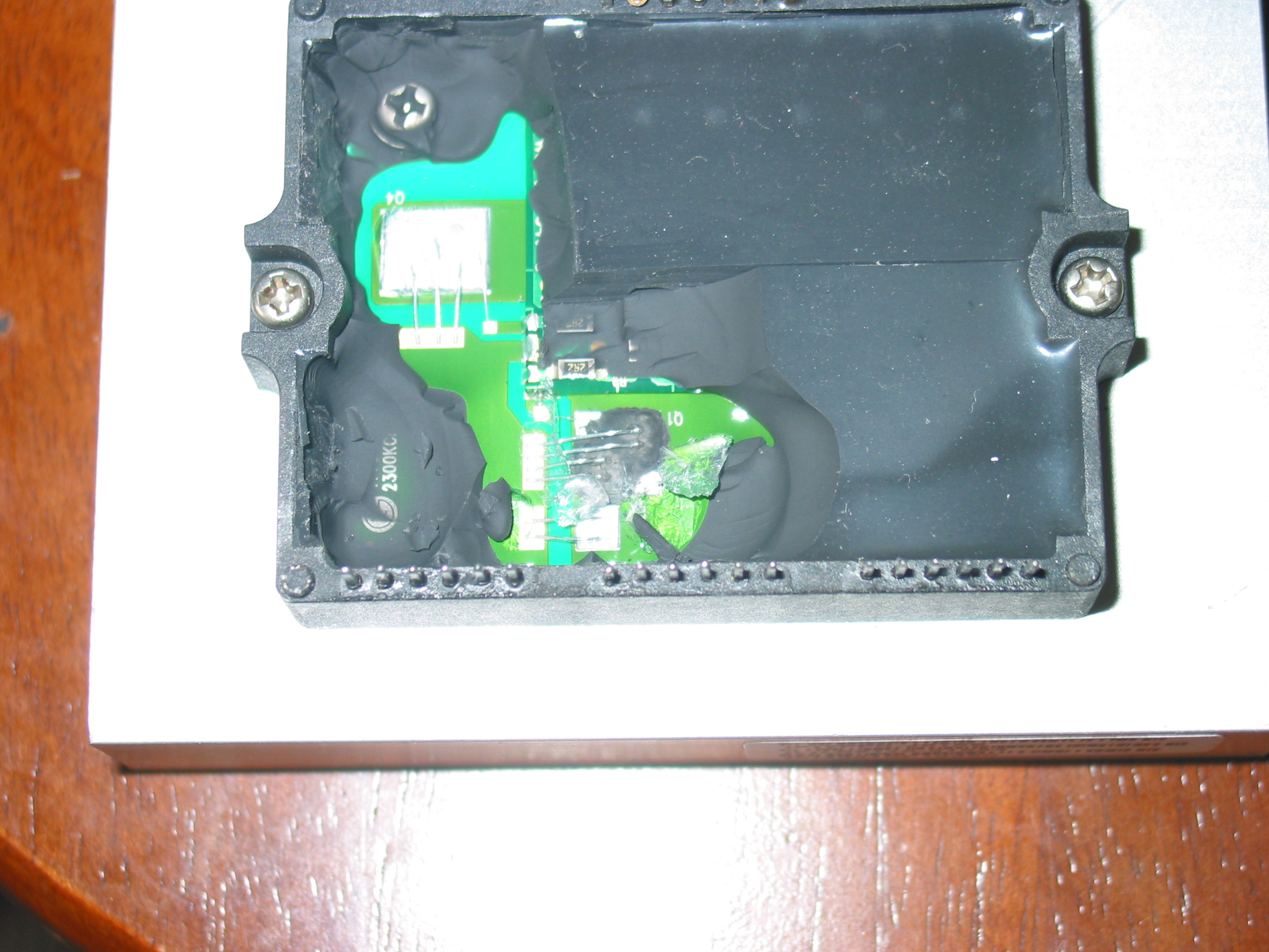
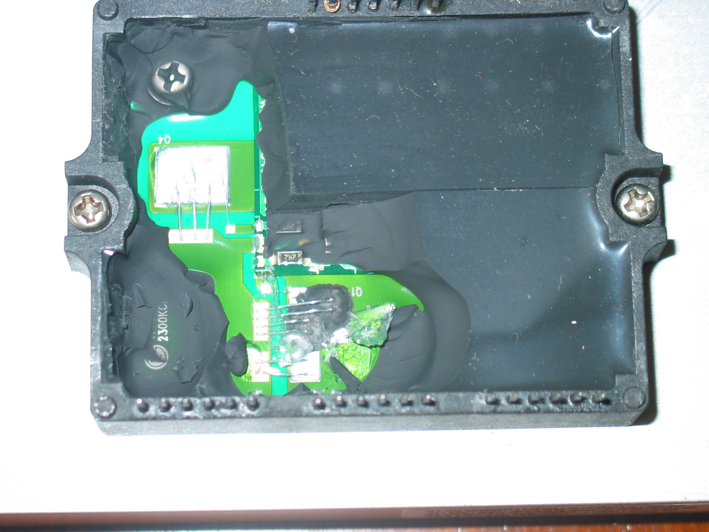
2) The 5V output on CN1 (the lowest 5 pins of the connector) provides power to all the logic functions needed when the TV is working. They flow through a power transistor located at the back of the board which carries both filter and control function.
Simply said, think of it as an operating switch which has 3 connectors - input, output and a controlling (gate) connector which tells it when to activate.
That transistor is apparently badly rated because on many of the boards we received it was bypassed by simply shorting the input and output and completely ignoring the switch control input:
While rude, this solution is a cheap and efficient one if you don't see the 5V at the connector of your board , but you see them on CN2.
If both of those fail to help you, we'll be glad to try our luck diagnosing and fixing your board for $50 or so.
Just send it over!