Dear Coppell TV Repair,
we purchased part # YPPD-J015B from your company through PayPal.
The item arrived and is defective. Please advise how we may return this part to you for exchange or refund.
Thank you.
The item arrived and is defective. Please advise how we may return this part to you for exchange or refund.
Thank you.
Since we sell J015C and not J15B and since the mix-up of a J015C and J016B is deadly, my first guess was that they had installed J015C as a replacement of J015B and, sure enough, it would have lasted a very short time.
I wrote back explaining that we pay premium for our J015C components (and we really do!) and that we haven't had a defective one in a very long time (and indeed we haven't!) and that perhaps they confused J015B with J015C. This is a common mistake which is the reason why in the listing for the YPPD-J015C sale we have multiple warnings about the need to use C versions for both IPM modules on the sustain board.
Here's the response:
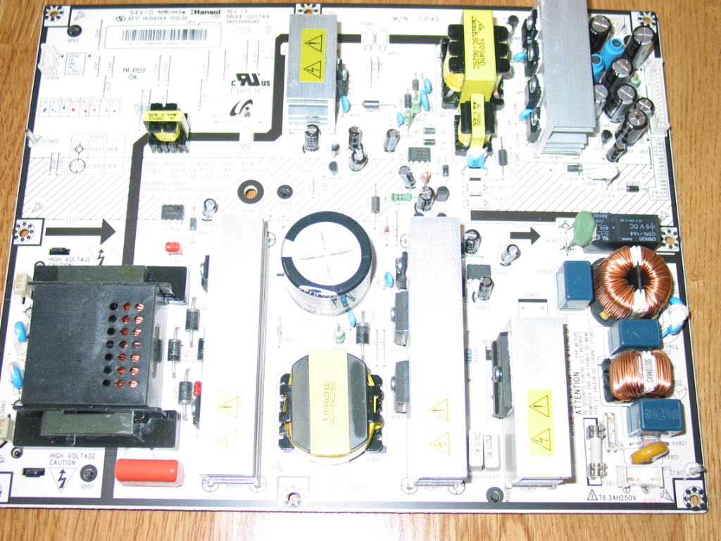
You are most certainly NOT correct in your assumptions. The part you sent us was NOT NEW. As soon as we received it my technician pointed out that there were imprints from the screws where it was formerly fitted and pinholes on the back of the silicone seal.
I told him to go ahead and use it because we had previously bought parts from your company with no problems.
The TV did not fail as you presume but has a negative video.
I do not dispute the experience of your company or the satisfaction of your clients. In the pas I was also a satisfied client. However, I resent your implications that we dot not know what we are doing here. we have been successfully servicing TV's here for the past 22 years and like Coppell TV we are highly trusted and respected.
I am telling you that the part you sold us is defective and would like your cooperation to return it for exchange or refund.
Now, I am posting the response without any changes. This way you can see that someone with 22 years of experience (and, frankly, that's more than us!) claims the part we sold them was used and defective.
You draw your conclusions and decide if you want to purchase from us. You were warned!
For the curious minds I'd like to point out that the sustain IPMs are NOT involved in forming the color of the picture on the display. They are responsible for the high-voltage impulses that power each individual row on the plasma, but NOT with the color.
Any defect in the sustain IPM will affect typically the brightness of the entire row, in fact the entire screen.
Other parts on the board, however - and they are, of course, related to the IPM - are responsible for using the color information to 1) control the IPM timing and 2) dispatch that information to the sustain buffers.
At the moment I will not say which are those components. I will only say that they go bad often when J015C shorts and need to be checked when J015C is replaced. (BTW this also confirms customer was right about my initial guess being incorrect; they had clearly used J015C and they had observed a common problem with a failed J015C).
What has happened at the end? Well they asked for a refund or replacement and they got a refund since a replacement would not have had an effect. Since they've been in the business for 22 years and they knew the part was defective (and we knew it wasn't) we kindly asked them to send it back. In order to avoid similar conversations in future we asked them to use a different vendor. As I said we pay top dollars for those parts and believe it or not there's a shortage of components - even at the high prices we pay - and a great supply of customers.
We also predicted they will observe the same result with the next IC they use.
We also predicted they will observe the same result with the next IC they use.
Now that I think about it, we didn't play it in the best possible way. We weren't quite service-oriented and instead of helping them solve their actual problem we got ambitious of proving they weren't right.
Then again what was their actual problem? It depends on where you look at it.
To me it all started with "The item arrived and is defective."
To me it all started with "The item arrived and is defective."
Here's my two cents: if you're a customer and you buy from supposedly respectable source (e.g. top-rated seller with a long history and lots of positive reviews) do not jump to conclusions if things don't go as you expect.
Try "I am having a problem, can you help me please?".
I'll be the first to admit the advice applies at 100% for yours truly.
Follow-up on October 6 2010: The J015C unit did arrive last night. I was impatient to test so I stayed late , put it on a board and, sure enough, it was working. So much for jumping into conclusions!
