"My Polaroid just died and after some research I found that it's usually the power supply and then I found your blog and learned that CoppellTVRepair repairs it. I opened up the TV, looked at the board and I indeed have R0804-0901. There are no swollen caps or broken elements that I see...I want to use your service, but I want to know I actually need it before I pay."
That's a fair statement. To start with, only about half the time it's the power supply that goes bad. The other half it's the main board and , at least for the time being, we can't help with that...with more than the helpful information I already posted a while ago about cross-referencing main boards from Polaroid and Memorex.
So it makes a lot of sense to test the power board instead of assuming it is dead.
And here is how:
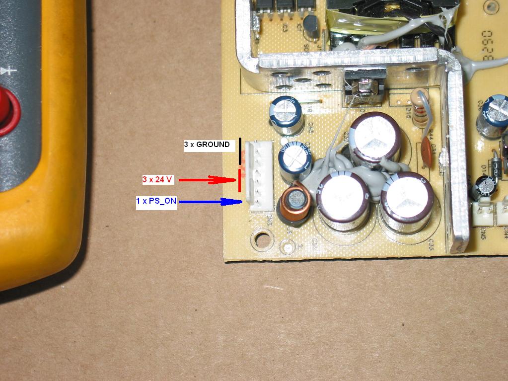
The R0804-0901 is extremely simple in regards to operation and outputs. Unlike most TV power supplies its only standby circuit produces 24V and those can be measured at any time - on or off - at connector CN3, where the first three pins are ground, the second three are +24V and the last one is used to turn on the secondary power source for the back lights:
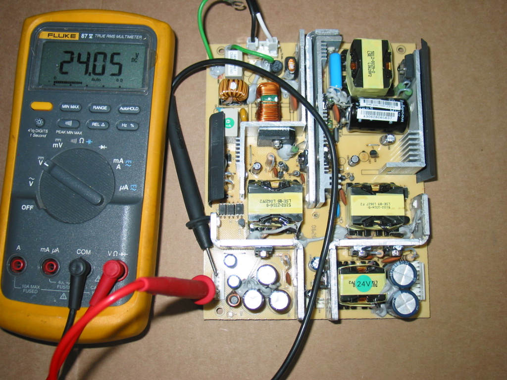
I measure the voltage by simply feeding power to the supply and sticking the meter probes in the connector:
Most of the time, if you have 24 volts there, your power supply is good.
Now if you want to be sure that everything works, then you also need to test the secondary output, which is at connector CN2 across the board.
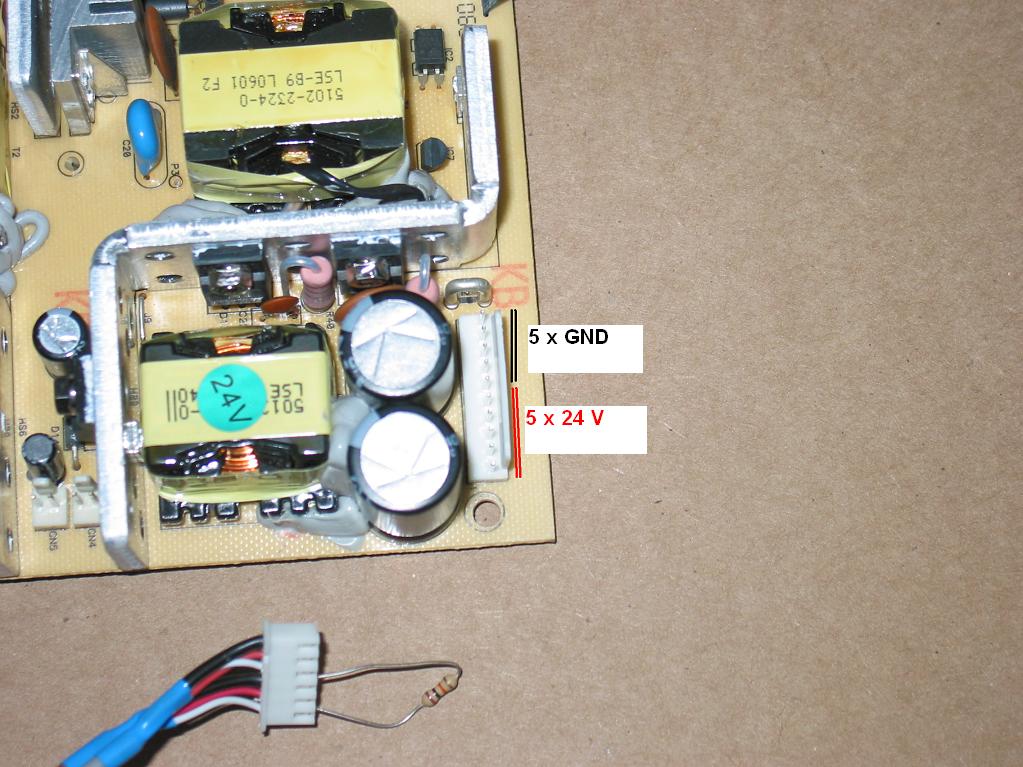
It is even simpler as it has 5 pins ground and 5 pins 24 volts (separate from the first ones!):
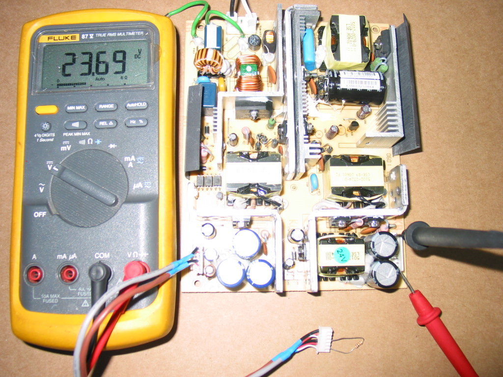
In order to do that, though, you need to turn that circuit on, which is done by connecting the PS_ON pin on the first connector (look above) to the primary +24V through a resistor.
Anywhere 1 kOhm to 10 kOhm should do.
On the picture below I had used a simple cable from another TV to allow me to easily connect the lowest pin to some of the ones above it through a resistor.
You will likely not have such a cable handy...but then again you only care about this test if your TV powers on and off, has sound, but there is no back light.


7 comments:
Dear coppell repair,
Please help I think I'm losing my marbles!!! I recently received my dads proview 3200. No power just sound out of the speakers and found your forum here on the net. I only had 12 volts on the cn3 connector so I ordered a power supply from Jimmy's and when it was installed I still had only 12v. I then wired a cord directly to the new power board and still only 12v on CN3. Now I don't know what to do, I did replaced the capacitors on the main board as stated in other blogs about this set. If you have any advise on further test I can do to repair this set it would be greatly appreciated.
I have the same PS above that has the constant 28V working fine, but no switched 28V. It is getting the +5V command signal to turn on. Doesn't look like the PWM for the switched 28V is getting a bias. Is there 2 separate PWMs? Is there a schematic available?
Thanks!!!
-Stephen B
You definitely put a new spin on a subject thats been I have read a few of the articles on your website now, and I really like your style of blogging. I added it to my favorites blog site list and will be checking back soon. Please check out my site as well and let me know what you think.
National Power Supply Engines
I liked the concept of your blog posts. It is very well portrayed as well as depicted.
National Power Supply Engines
Thanks, this turn on trick helped me find defective D11 for a blue flashing led no function problem
If your not getting the 24v to the bottom of the power that means the power supply is good
Is bad
Post a Comment