Friday, January 7, 2011

Samsung 214T LS21BRBAB does not power / blinks once

This is a story about pragmatism. A tiny bit of knowledge sneaks it at some point, but for the most part it's just a story. If you expect ground breaking discoveries, mysterious occurrences or erotic adventures then you should move to some of the next posts. You may have better chances there. Bear in mind I am not promising anything.

A local customer called on the phone and asked if we can fix 21'' LCD monitor.

We told him it's probably cheaper to buy a new one these days, but he said he's curious what could it be and is ready to pay our minimal service fee for 32'' LCD TVs for us to take a look.

Monitor was 21'' Samsung 214T [R] S, model code LS21BRBAB/XAA and as customer told us he had looked it up on Google and, upon finding a common failure in the power board caused by bad capacitors, has replaced them to no success. So he wanted us to take a look and even if we can't fix it he'd pay us $55.

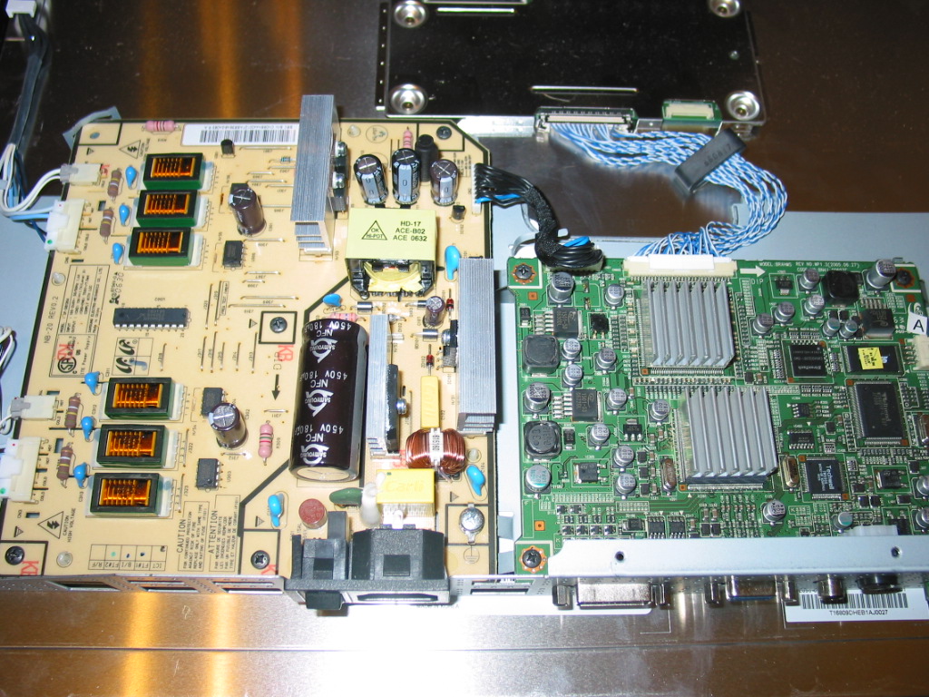
For your viewing pleasure, this is how Samsung 214T looks inside:


For the technically challenged and the rest from the normal side of the humanity the brighter thing on the left is a power board and the green thing on the right is the main board.

The power board incorporates in it functionality for providing the special needs of the florescent lamps that provide backlight for the LCD assembly.

Well long story short, the customer has replaced all caps on board and, from the look of it, has done it well.

The monitor was powering on all right, then the display would flash for a split second and instantly turn back again. Monitor would power on and off, just wouldn't stay bright.

Many LCD TVs have the same symptom and the cause us, overwhelmingly, in the circuits that provide power to the back light lamps. In large TVs they are often on a separate board, but smaller TVs and monitors they are sometimes incorporated in the main board just as shown here.

There are several reasons why something like that would happen and before troubleshooting it I took a quick peek at the power board. I was looking for a board label, something that would allow me to look it up on eBay and see what would it cost.
What I had come across was a label NB-20 towards the top of the board.

So I looked that up and a single result showed up offering me a "TESTED, WORKING POWER SUPPLY BOARD NB-20". It was asking $69.95 plus $9.95 shipping. Here's the actual link.(bear in mind it may be invalid by the time you read this).

$80 is a lot of money for a 21'' LCD TV. Way too much in my book.

But then again the link mentions that this is board "IP-58130A", so I searched for that.

Bingo! $26.99 direct from China, 20,000 sales seller, 98.8% feedback.

Reserved as I am , I think this is a no brainer.

I put together the TV as quick as possible and plan on telling the customer to pay me our standard fee less $27 and get a new board from there.

It's not about the money...and I know I can fix the damn board.

I just don't think I can do it the first time for under $27.

Friday, December 10, 2010

If you consider buying parts from China consider this

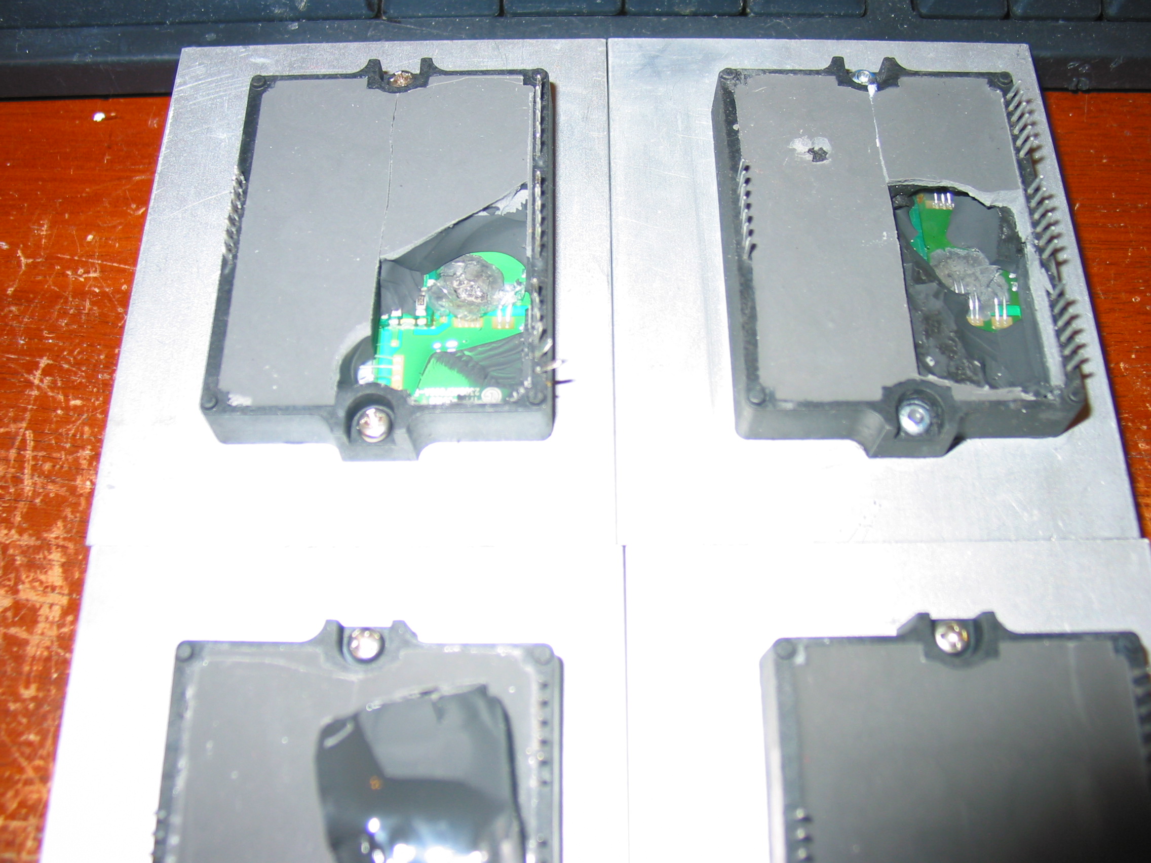
Next time a customer complains that they received some of our ICs with bent legs I swear I'll send them here to
see some of the REAL problems when purchasing parts.

All of the below are sold to as for "new" and, if you can believe it, prices are as for "new".

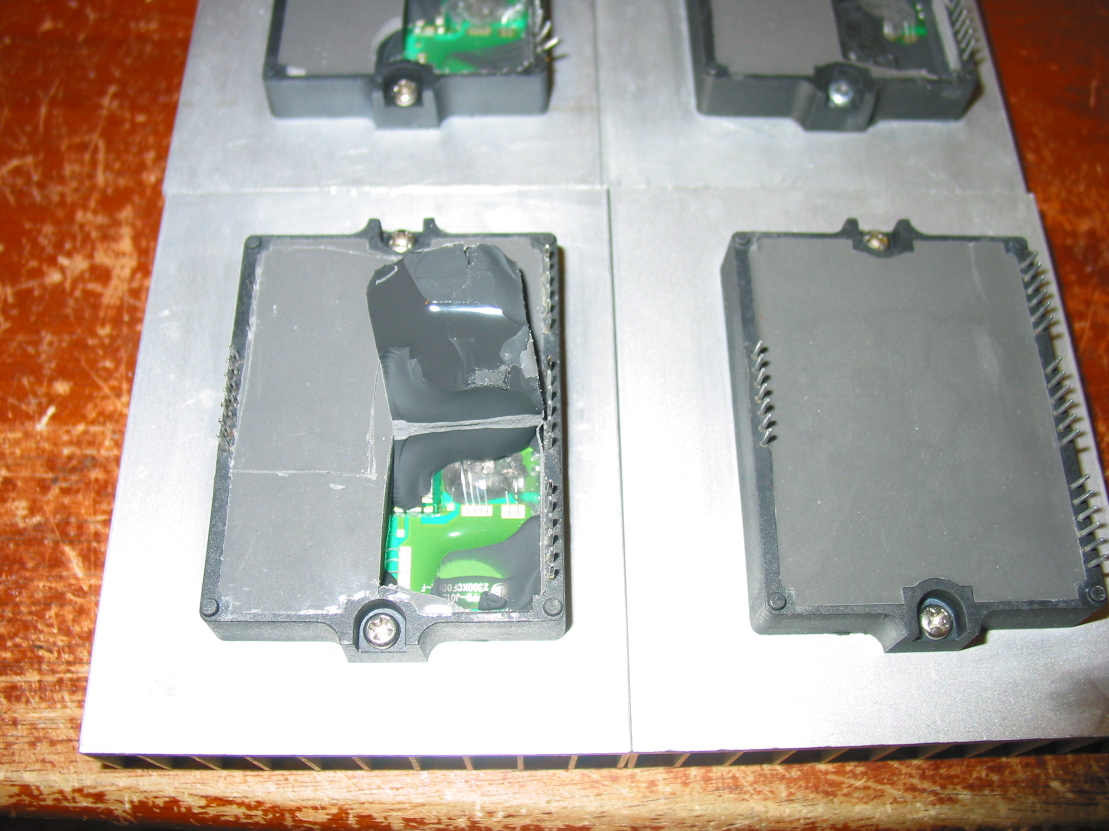
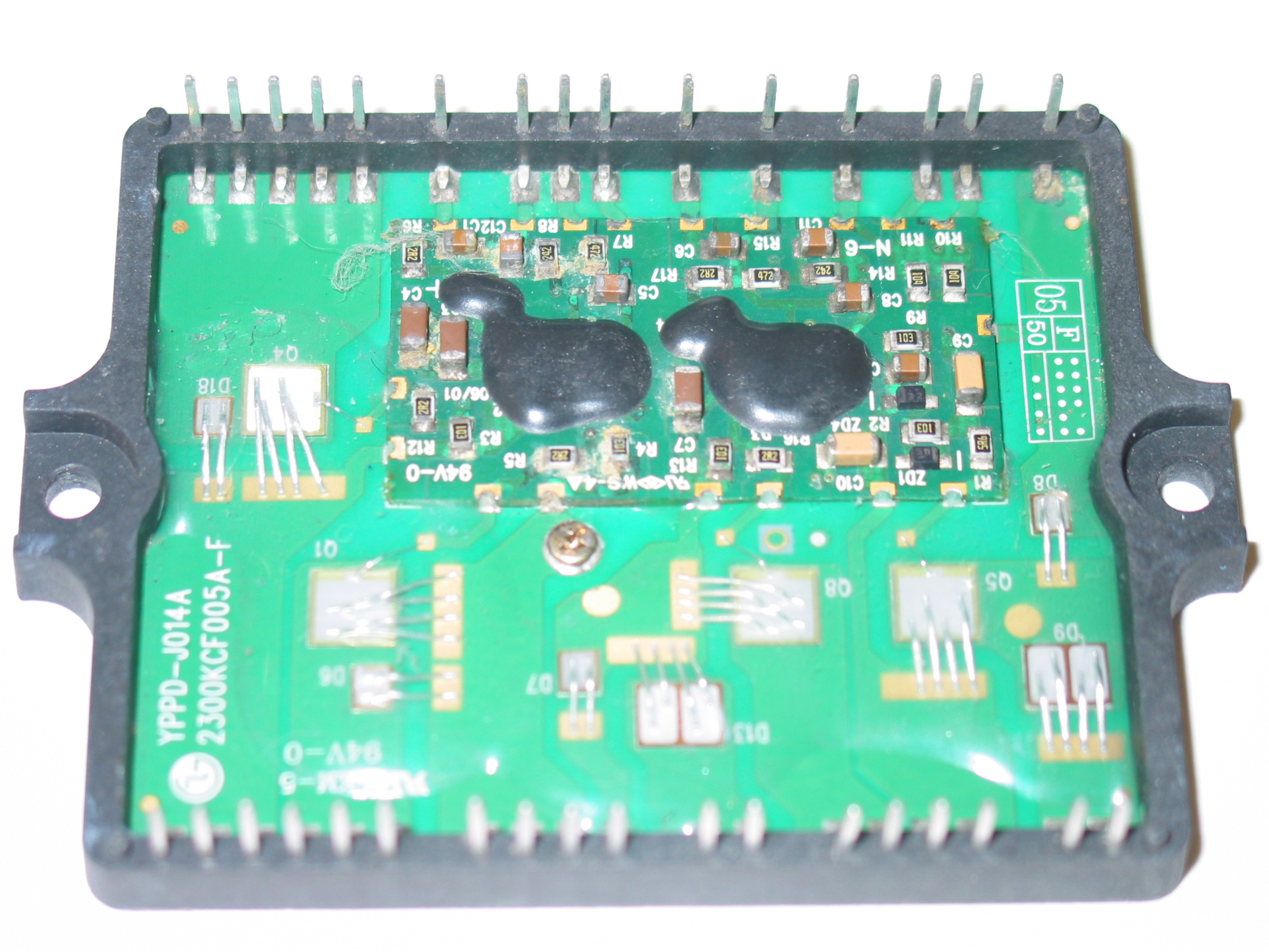
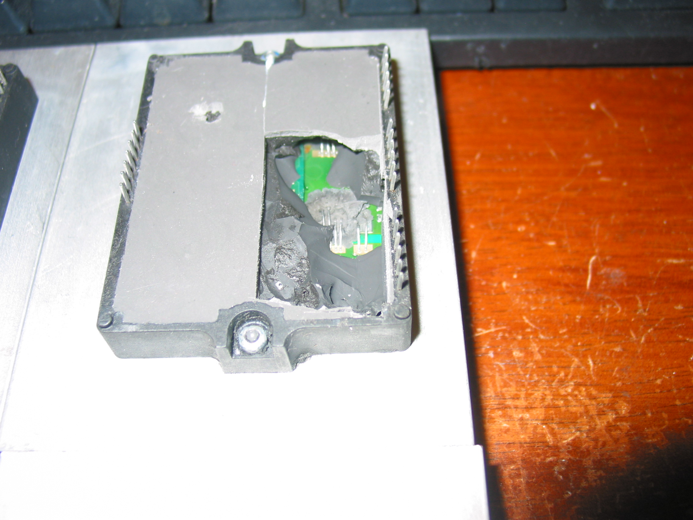
After 2 didn't work right out of the box we took the freed to cut them open and then picked another two from the same box and opened them WITHOUT INSTALLING AND TRYING THEM FIRST.

I guess it is not hard to predict what the fourth IC on the image below will look like inside, is it?


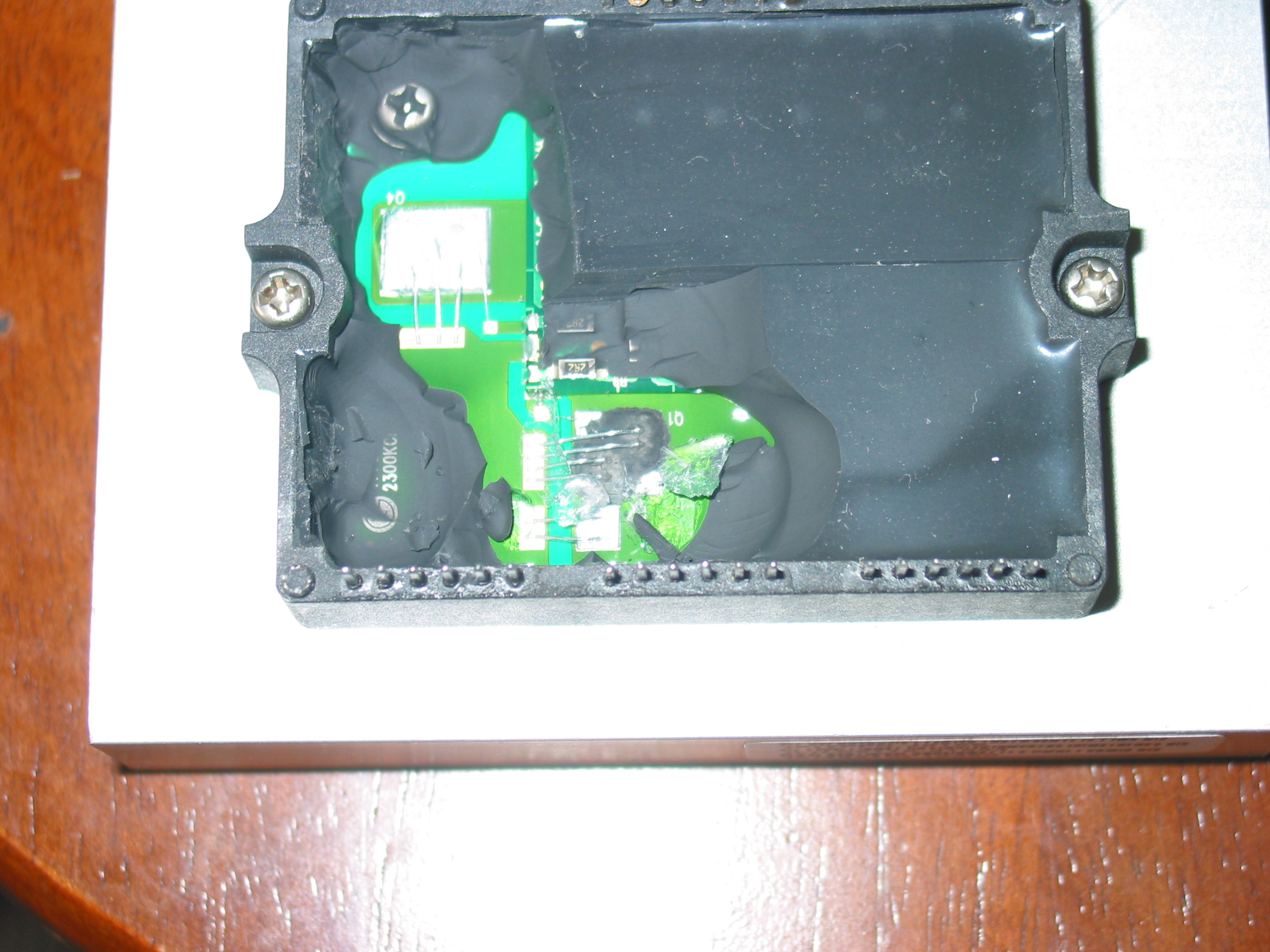
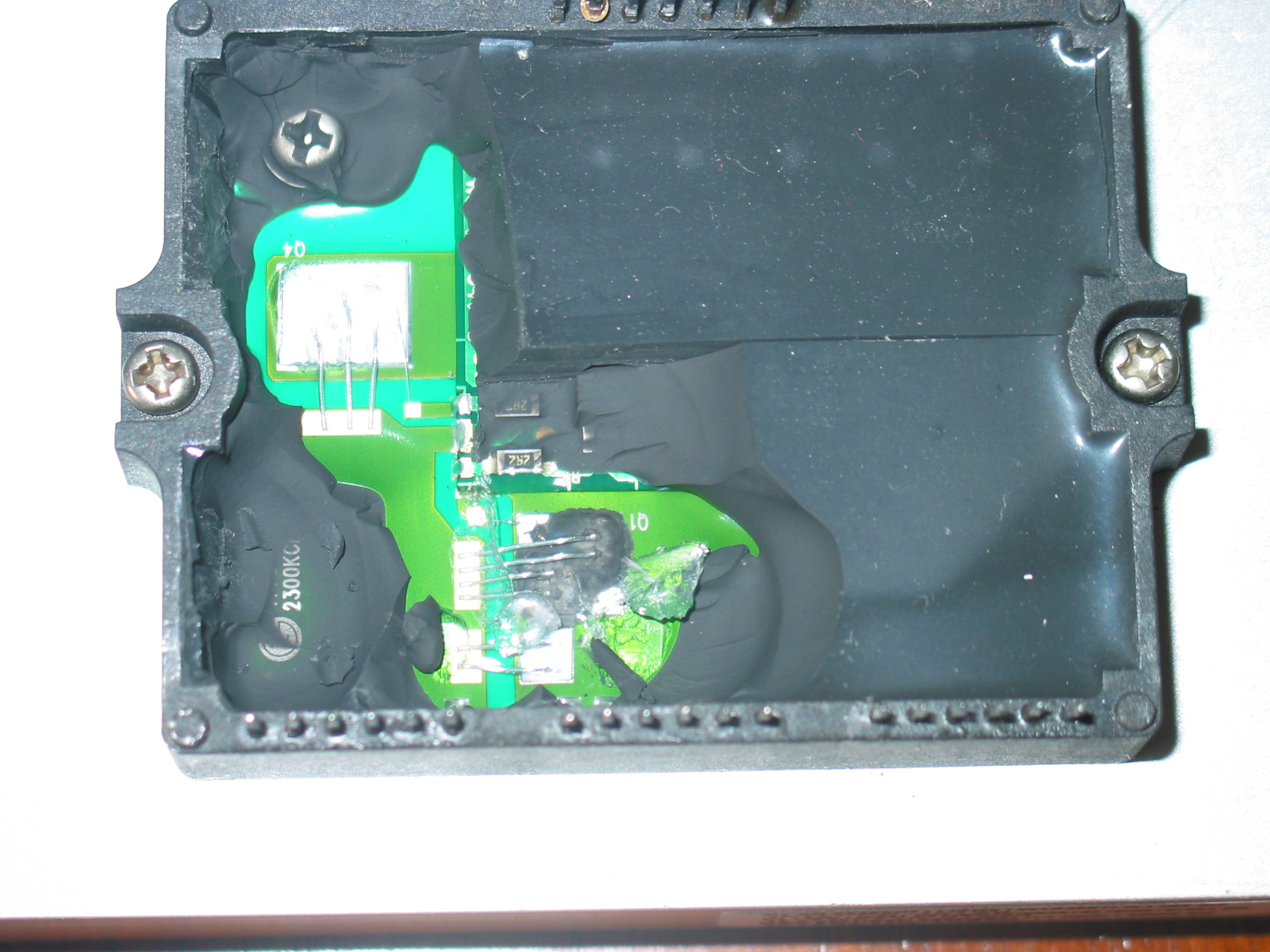
Rust on ESD components, rust on pin solder connections...

Notice how the original black filling of the IC is covered with a thin layer of a gray one.


There are several take home lessons from this:

1) Buying from China is risky. And it's not because your Chinese partner necessarily wants to trick you. Those parts were received from a company we've been working with for some time with and we do not doubt their honesty.
The problem is they themselves aren't good enough to filter the bad parts that they purchase.
And because we've tried several different vendors we can say this is the common situation out there.

2) It pays for a customer to purchase parts from a company that actually uses them in its own work. If we had sold those parts to customers and we haven't had to use them ourselves we'd probably be doubting our own customers' honesty when they call back and say that apparently brand new working parts do not work.
But since we use them ourselves we act as a first line of quality assurance for customers.
When the product you're buying is not only valuable, but greatly affects the time you spend on a job it does matter to know you're getting quality stuff.

3) Next time you want to save a penny - or even a dollar - by buying directly from China consider all the headaches that a local American company saves you. Not to say all American companies are perfectly well equipped to know the difference between good and bad parts...not at all.
But it's it's still a whole lot easier to hold a company responsible in America than in China.
And frankly, if there was an American company that could offer us the parts we need at decent prices we'd sure be buying them from here!

Thursday, December 9, 2010

MLT166A POWER BOARD TEST AND REPAIR - AKAI LCT2701AD and LCT2701TD

A company has sent us a bunch of those boards to repair and we are sharing some of our expertise on how to test and repair them.

Those supplies are used in AKAI LCT2701AD and AKAI LCT2701TD models.


(If you need Coppell TV Repair to repair your power board please first make sure it needs repair as per the below instructions and then contact us to arrange repair. From what we learned odds are good it may indeed be faulty.)


Indeed, this is apparently a poorly made power board because all of the ones that we received had been previously serviced already.

So how do you know if it works?

TESTING POWER BOARD MLT166A
When connected to 110V AC through the main connector CON0 (at the lower right corner on the picture) the board is only supposed to produce 5V standby voltage. This shows up on connector CON2 which is the second white connector from the top on the left side of the board. It is between the two heat sinks and next to the order of three capacitors EC18, EC19 and EC20.

When testing the board we recommend that you disconnect all load from it, i.e. unplug all connectors except the one that feeds AC power in.

The CON2 connector has 6 pins organized in three groups of two pins like this (starting from the top):

* STB (aka PS_ON)
* STB
* GND
* GND
* +5V STB
* +5V STB

The lowest two pins is where you get the standby 5V power. You will need a digital multimeter to measure them. It is OK if reading is 10% off, i. e. anything between 4.5 and 5.5 V will do as long as it is stable.
To measure the voltage you connect one probe to either of the +5V STB pins and the other to either of the GND pins.

To activate the power supply (which is what happens when you pres the POWER ON button on your TV) you need to pass the 5V to any of the two STB pins.
We do that by simply soldering a resistor of about 100 Ohm between the two opposite pins of CON2, but you can as well just short them - in this particular case.

Once you do, the board should start making a humming noise and the rest of the voltages should show up:

CON1 has 3 sections - 3 pins for +12V, 3 pins for GROUND and the rest for +5V:
* +12V
* +12V
* +12V
* GND
* GND
* GND
* +5V
....

CON3 and CON4 each have half of their pins for GND and other half for +24V needed for the inverter boards.

If you get all those voltages then your power board does not need a serious servicing.

COMMON PROBLEMS WITH MLT166A

1) Probably the single most common problem with those boards are bad electrolytic capacitors. You should check and replace those regardless of whether the above test passes or fails. Bad capacitors can change board's behavior under load and can render it useless even if it passes the simple no-load test.


Electrolytic capacitors are the cylinders with shiny tops that can be seen all over the board.

Bad ones can usually be spotted by their bulged tops compared to the other, normally flat ones.


Behind the above mentioned connector CN2, for example, is a trio of capacitors that had to be replaced (or was already replaced) on any single board that we've seen. Those are EC18, EC19 and EC20.
Originally they are rated 1000 uF / 10V each.
If you need to replace them, you should replace them with 105 degrees , 1000 uF or slightly more and at least 10V rated capacitors - the higher voltage, the better (bear in mind they get larger though).

Since EC18 and EC19 work in parallel it is also completely acceptable to replace both of them with a single 2200 uF / 25V capacitor that will work better and last longer.

One one of the boards we serviced we've also had EC11 apparently bulged so we had to replace it as well.

On your board you may have yet a different one that needs to be replaced.

If you need parts, let us know and we can sell and send them to you!

2) The 5V output on CN1 (the lowest 5 pins of the connector) provides power to all the logic functions needed when the TV is working. They flow through a power transistor located at the back of the board which carries both filter and control function.

Simply said, think of it as an operating switch which has 3 connectors - input, output and a controlling (gate) connector which tells it when to activate.

That transistor is apparently badly rated because on many of the boards we received it was bypassed by simply shorting the input and output and completely ignoring the switch control input:


While rude, this solution is a cheap and efficient one if you don't see the 5V at the connector of your board , but you see them on CN2.

If both of those fail to help you, we'll be glad to try our luck diagnosing and fixing your board for $50 or so.
Just send it over!

Wednesday, November 10, 2010

MLT070AX repair problem for Polaroid 3700 / FLM-373B or Are They Crazy

I find more and more of my daily time being taken by users and technicians from all around the country who have a little question to ask.

I am new to all this, I guess it is all part of the job.

Except it pulls you away from the job!

Where was I?

Oh yes: a few days ago someone called and said that since we repair power boards MGMEET MLT186 and MLT186B then we almost certainly should be able to repair MGMEET MLT070AX used in his Polaroid 3700 (same as Polaroid FLM-373B). This on the basis of them looking very similar.

This is how MGMEET MLT070AX looks:


The caller somehow tricked us into telling him to send the board over here so we can take our chances. I am almost certain we warned him we may fail, but he put a spell on us by simply saying no we can't. Even worse, he used the spell and made us promise we'll fix it for the same price that we had listed for its smaller nephews MLT186 and MLT186B.

Well the board arrived and I am relieved to say we were able to hold our promise.

Just do not think we are proud with it OK?

And with the explanation why I am actually getting to the heart of this posting.

Oh, by the way, if you need your MLT070AX fixed feel free to contact Coppell TV Repair, before or after reading the rest of the story.

So we fixed the board for a total of $58, which was the price for which we have repair listed for MLT186 and MLT186B.

Can you guess how much was the board for sale on the free market?

The lowest I could find available was $120 before delivery! Most were $130+.

For a power board of a 37'' 720p LCD TV of insignificant brand?!

DO THOSE COMPANIES/PEOPLE LIVE ON THE SAME CONTINENT THAT I DO?!

My local Craigslist offers 37'' Samsung LCD 720p for $250, a year old 37'' LCD Vizio w/ remote for $210, LG 37'' LCD for $230 and so on.

You do the math.

I guess not everyone has or uses Craigslist.

But then again holidays are coming.

And would advise any customer to NOT pay more than $70-$80 for having their board repaired or replaced OR, when that doesn't work (because there are times when it doesn't) to keep the money and apply them towards the purchase of a new TV.

Prices are sure to go down, at least this holiday season and likely in the near future:
http://news.yahoo.com/s/ap/20101029/ap_on_hi_te/us_tec_lcd_tvs_falling_prices

Monday, November 1, 2010

Power board MLT186B from ILO-32HD - how to test

Coppell TV Repair services MLT186B from ILO-32HD and as with many other services we sometimes receive boards that are actually functional.

This post should help both those who wonder if their ILO-32HD is dead because of the power board or the main board as well as those who receive a serviced power board from us and think it was not properly serviced.

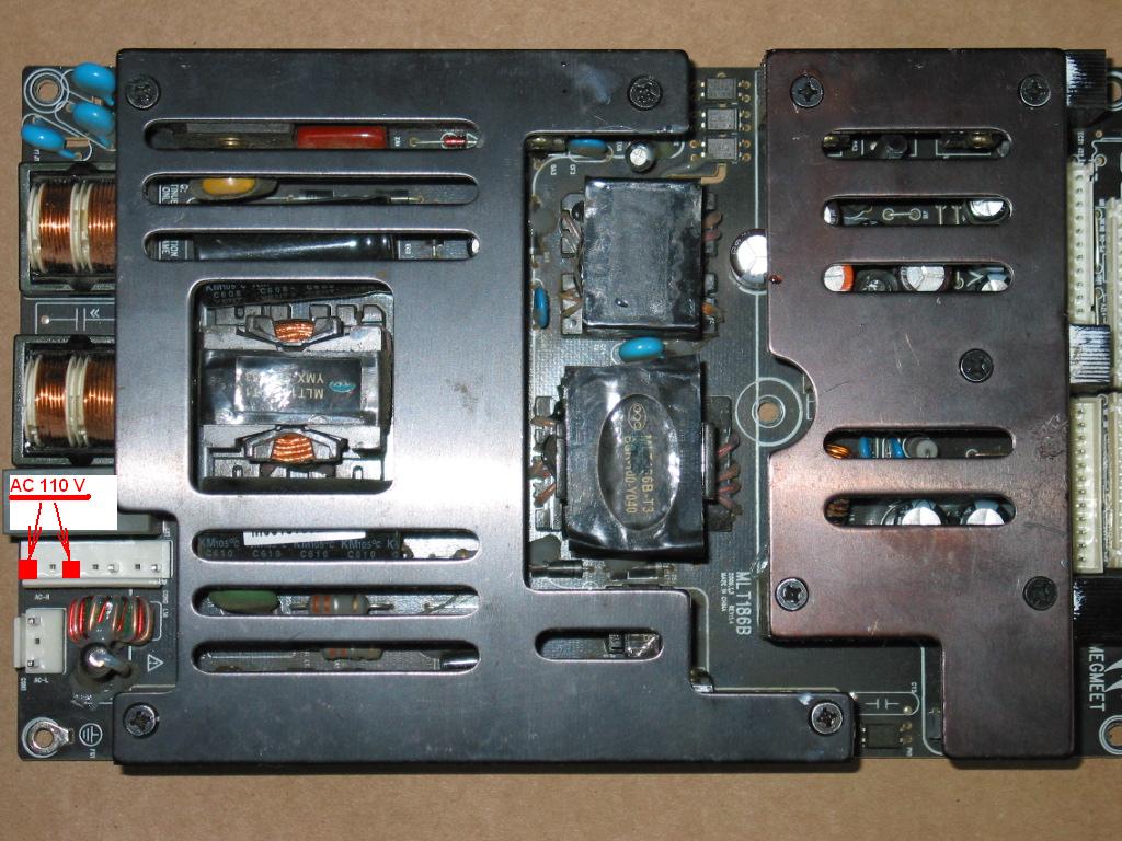
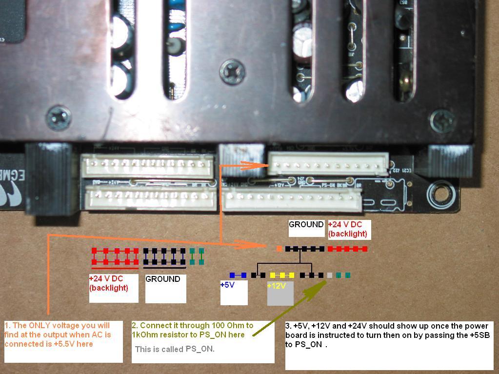
MLT186B is relatively simple power board , producing one standby always on output voltage of 5V (can be a bit more without load, it's OK) and, upon instruction from the main board, activates the actual driving voltages of +5V, +12V and +24V.

(Note: a similar article for power board MLT186 can be found here.)

One uncommon thing about it is that the input AC voltage is supplied through an external button switch. Unlike most other power boards we've seen there are actually TWO connectors for AC input - one for the main input and another one, which takes the power from the main input, routes it through a button and returns it back to the board. For testing purposes this can all be circumvented by directly passing power to the appropriate return pins.

Below are two pictures with diagrams that should help you test your board.

The hardest part will probably be the connection between the 5V standby and the PWR_ON pins.
Probably the easiest way to do it is to use a resistor and stuck its pins in the connectors that are already in the power board. Unfortunately you'd need to jump to the nearest RadioShack or buy such a resistor from us or another place. It is also possible to directly short the pins, but we advise against that practice in general. Always use resistor as you never know how smart and protective were the people who designed the board in the first place!


Monday, October 25, 2010

LJ92-01200A / LJ41-02759A - the truth according to me (feat. LJ92-01203A / LJ41-02761A and LJ92-01202A / LJ41-02760A with 6 ICs)

(December 2012 update: a set of replacement Y-Main and two brand new, OEM buffers is now available at our store for an exchange service. Still, please read the article before proceeding there!

(February 2013 update: our store now has listings for both the upper buffer LJ92-01202A and lower buffer LJ92-01203A - used, but tested and functional, offerred as-is; make sure you read this article and offer description before buying!)
 
I've been planning to post this for a long time, but various things have been stopping me until today.

This article summarizes some of my experience with the infamous Samsung 42'' plasma trio of boards:
1) The Y Main sustain LJ92-01200A / LJ41-02759A
2) The upper and lower buffer boards  LJ92-01203A / LJ41-02761A and LJ92-01202A / LJ41-02760A


(Note: this article is about the A1, A2, A3, A4 and A5 revisions manufactured in 2006/2007. In 2010 Samsung has released new versions of those boards with four instead of six buffer ICs. It is far too early to know if they have the same flaws as the old ones. They have, for example, apparently different design and implementation and newer ICs may be better than the older SN755867 and SN755870.)

We at Coppell TV Repair often receive questions about those.

Do we repair buffer boards?
How much would it cost to have all 3 replaced?
Do we mind sharing what goes bad on the Y-Main? (this is usually from other technicians)
Are the new buffers better?
Should the customer invest in repair or junk the whole TV?

Some of those questions do not have simple straightforward answers.

I really wish it was that easy. But it isn't, not unless you want to take the king's approach to it and replace everything. Which, as reality shows, tends to be rather expensive exercise.

I truly believe that one of the humanity's major flaws is that it often tries to fix something without understanding what actually had been broken in the first place. Stepping more on the gas instead of releasing the hand brake , treating kids for ADD instead of spending more time with them or taking pills for depression instead of stopping to listen and watch to the media reporting rapes, kills, recession and end of the world in general....just a few from the top of my head.

Sorry, got carried away.

I want to tell you what happens and how it happens.

Don't forget, it is all according to me and although I have a graduate in electronics I am much better in software than hardware.
Some of my guesses may be wrong...if you catch one I'd appreciate bringing it to my attention.

Let's start with


PROBLEMS CAUSED BY A BUFFER FAILURE


There are two possible problems here: when a buffer fails without shorting and when a buffer fails completely.

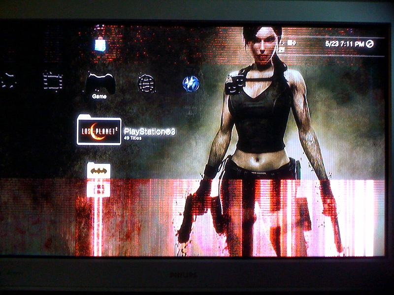
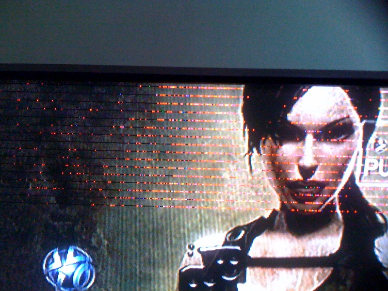
When a buffer fails without shorting it typically results in horizontal pink/purple lines. They can appear at isolated portions of the screen or on the whole screen.

Such horizontal lines of pink / red sparkles is clearly a buffer on its way out. To see it full screen just click on an image. (screen shots submitted by customer Jason Stubbs , a man with a good taste :-)):

This problem can NOT be  detected with a meter or at least I do not know how, but as I said above if you see those lines you your buffers need to be replaced.

What if only the upper/lower half of the screen has those? Well, read on as to why it happens and you'll understand.


The SECOND, ultimate and actually more popular buffer failure is shortage.

While the pink lines described above is only a partial failure which damages the control logic in the buffer ICs, but still doesn't completely kill them this one does.

A full failure is caused by a more massive meltdown in the IC during shortage and usually results in a an electrical shortage between the power lines of the buffer.

(If you want to check if your buffer is shorted use the technique described in an earlier post.)

A burned buffer usually takes the sustain down and since both buffers are on the same power track without separation one failed buffer usually damages the other one as well.

But why does it all happen in the first place?

Because electronics wears out.

Literally.

I have two theories on what exactly is wearing out more: one is the semiconductor  junctions inside the buffer board ICs are wearing out because of the temperature differences between state at rest and state at work: when they work they get hot, the matter expands and changes structure, even by a tiny little bit, then when it cools off it shrinks and the little change remains. Over time, a micro-space develops as a defect in the semiconductor junction which one day leads to a shortage.

The other theory is that the insulation material they use for covering the IC pins changes properties over time, allowing for a high-voltage spark to jump from one pin to another, i.e. from a high-voltage output to a low-voltage power supply or control pin.

Over time I started leaning more towards the first theory as the same thing tends to happen in other components that do not have silicon insulation over their pins.

Each theory might be wrong, of course, but both are too good to explain what happens to ignore :-)

So the IC burns, melts and shorts.

That causes a momentarily overload to the Y sustain board which also burns one or more output components.


Finally, since the two buffers share common data and power line without separation any high-voltage jumping to the shared low-voltage power or data tracks tends to damage whatever it finds there that is not designed to handle it. Imagine placing 120V on a 5V data line....what do you expect?!

Which means that whenever a buffer shorts, usually all three boards end up being damaged!

The second buffer is not always shorted. Sometimes - in fact most of the times - it looks like normal, but will burn upon its first run in real condition.

Conclusion 1? When a failure is caused by a burned buffer LJ92-01202A or LJ92-01203A it is best to replace BOTH buffers.

Doesn't sound convincing? Well lets then empower the real heavy artillery, something very simple we almost said it plain, but you missed it:


Buffers wear out! Literally.

If our explanation is right and the silicone insulation on the buffers wears out due to the high temperature....until one of the buffers doesn't hold any more....how much longer do you think the other buffer will be able to carry on?

Think of it this way: if say the front two tires on your car wear out to a point where one of them tears out while driving...will you replace only that tire? And why?

Knowing that the failure of one buffer carries high risks of taking down the other...and knowing the buffer prices (which are anything but low) it's a no-brainer!


REINFORCED CONCLUSION 1: When a failure is caused by a burned LJ92-01202A or LJ92-01203A buffer it is BEST to replace BOTH buffers.
 
 Note: Sometimes the buffer defects in a way that does not immediately result in a complete short, but rather in a visual defect represented by pink / red sparkles in horizontal lines on the screen that vary from 1/6 of the display to the full display. When it is on the full display this can also be confused with another popular problem which has nothing to do with the buffers, but rather the Y sustain board.


Note 2: Buffer boards can be repaired sometimes, however most of the time it doesn't make practical sense for the very same reason for which it is best to replace both buffers when one dies: all ICs on the buffer board have been wearing out together and replacing one or two of them at a time, while fixing the problem temporarily, does nothing to prevent the soon-expected failure from another IC.
And replacing all 6 usually costs more than buying a new buffer.

While there is still what to be said about those buffers, we'll wrap it up for now and will switch our attention to

PROBLEMS WITH THE MAIN SUSTAIN BOARD LJ92-01200A

The same truth that holds for the buffers also holds for the sustain board  LJ92-01200A  (and in fact for all electronics) - heat wears them out.

But before we get to that we'll start with the one problem that's not caused by the Y sustain itself:

When Y Main sustain LJ92-01200A is damaged by a burned buffer
As we said earlier when a buffer shorts it usually takes down the sustain along with it.
Once damaged, the sustain may be damaged in a way such that, if you install new buffers, it will kill them on the first run.
When we say may we mean it happens. Not too often but still often enough.
Hence:

CONCLUSION 2: WHEN A BUFFER FAILS IT IS IMPERATIVE TO CHECK AND, IF NECESSARY, REPAIR Y SUSTAIN MAIN LJ92-01200A.

Note: This is the only Y sustain failure that I know of as of the time of this writing that presents a danger to the buffer boards!

I hope I will be forgiven for not telling you how exactly to repair this failure. I'll only say there are several common scenarios and information for some if not all of them is likely available around the Net.
As I've mentioned before we know there are other technicians who monitor this blog and start competing with our services on Internet based on what they learn...you get the point.

(Frankly, no offense meant, but from my contacts in the past months with various such technicians around the country I think they don't even know most of what's in this article...but that's another story; and still those are better than the ones reading what others say and then stating it on their listings and not giving credit to their sources!)

Pay attention, though, that the sustain does not fail 100% of the times when a buffer fails. In the tens if not hundreds of boards that we've serviced I can recall two cases where we had both buffers burn, but the sustain still working.

Just a reminder that nothing that we say is set in stone :-)

Now, off to the other Y main sustain problems:

IS THE MAIN IC BURNED ON THE Y SUSTAIN MAIN LJ92-01200A?


While it is bound to happen sooner or later for the same reason for which most of the plasma sustain boards designed and produced at this point in time.
People - both home DIY self-repairmen and professional technicians - often think the IC has failed when in fact it has not (it's only been a buffer failure, hehe!).

Fact: when main IC on Y SUSTAIN MAIN LJ92-01200A fails, it usually results in a blown fuse F5004.

This is the largest fuse on board located right next to the IC and above the power connector.

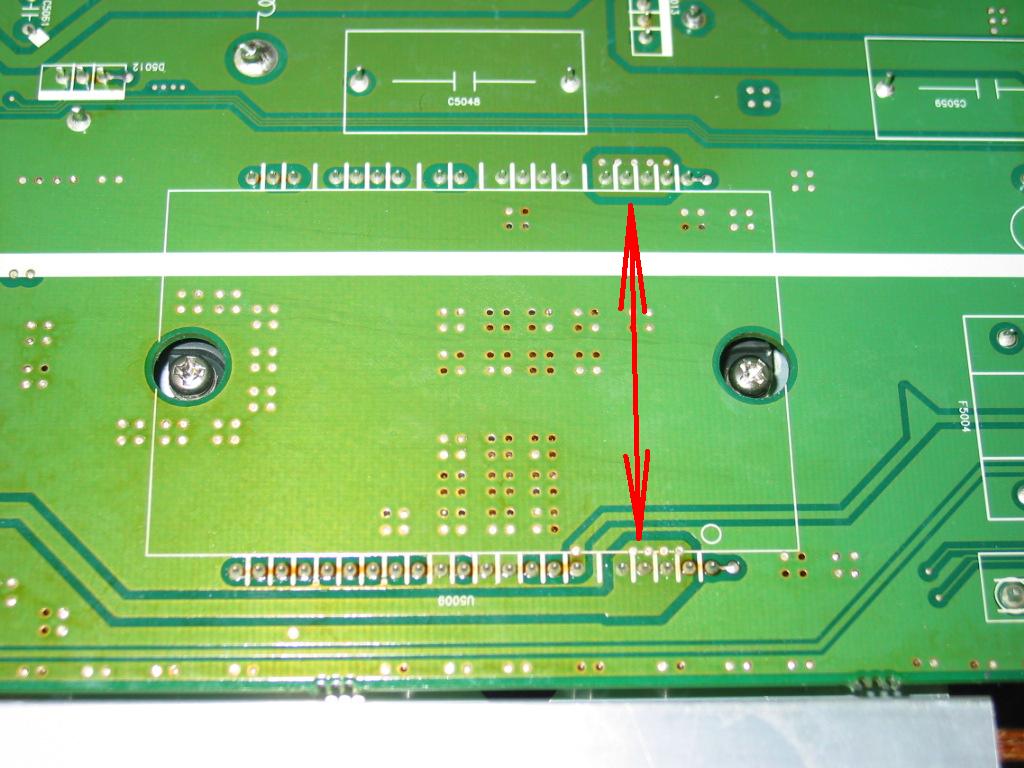
Another indication for the IC failure is a short between two groups of legs as shown below:


OTHER PROBLEMS WITH SUSTAIN MAIN LJ92-01200A

When it comes to problems this is one of the most versatile boards I've seen.
* Nearly all electrolytic capacitors bar the largest two can be seen swallowed and/or defected.
* Power stabilizers may fail, taking down other components along with them
* Output current amplifier FETs may fail (the ones under the smallest of all 3 heat sinks) possibly taking down other components along with them

Chances are I am missing some.


It's getting very late here and I think I'll stop now. I may write a follow-up or edit this article to present general conclusions.

But, in short, it helps to understand why we are asking for all three boards to move together, why most of the time we advise people to replace both buffer boards and why in the rare cases when at least one of them is working we spend a lot of time trying to educate them about the risks they're taking with replacing just one of the buffers.


Hope you understand.

And, if you're service technician, hope you link to this article!
Sunday, October 24, 2010

DELL W4201C HD powers on / off no picture - how to fix

This article describes a common problem and fix to all DELL W4201C HD plasma TVs. We've done enough such fixes to realize this is a serial defect that is going to be present in most if not all of these TVs.

5 May 2011 update: The same symptoms and solution apply to DELL W3201C, DELL W5001C and DELL W4201C!


You will benefit from doing it even if the actual problem with the TV turns out to be different (which is always possible).

If you can't do this on your own you can send the power board to Coppell TV Repair and we will do it for you for a very reasonable fee.
(or you can send it to one of the other technicians who read this blog, educate themselves and start offering the same service; we can name a few.)

Anyway, let us start with saying that the DELL W4201C is a Samsung plasma TV sold under the DELL brand.

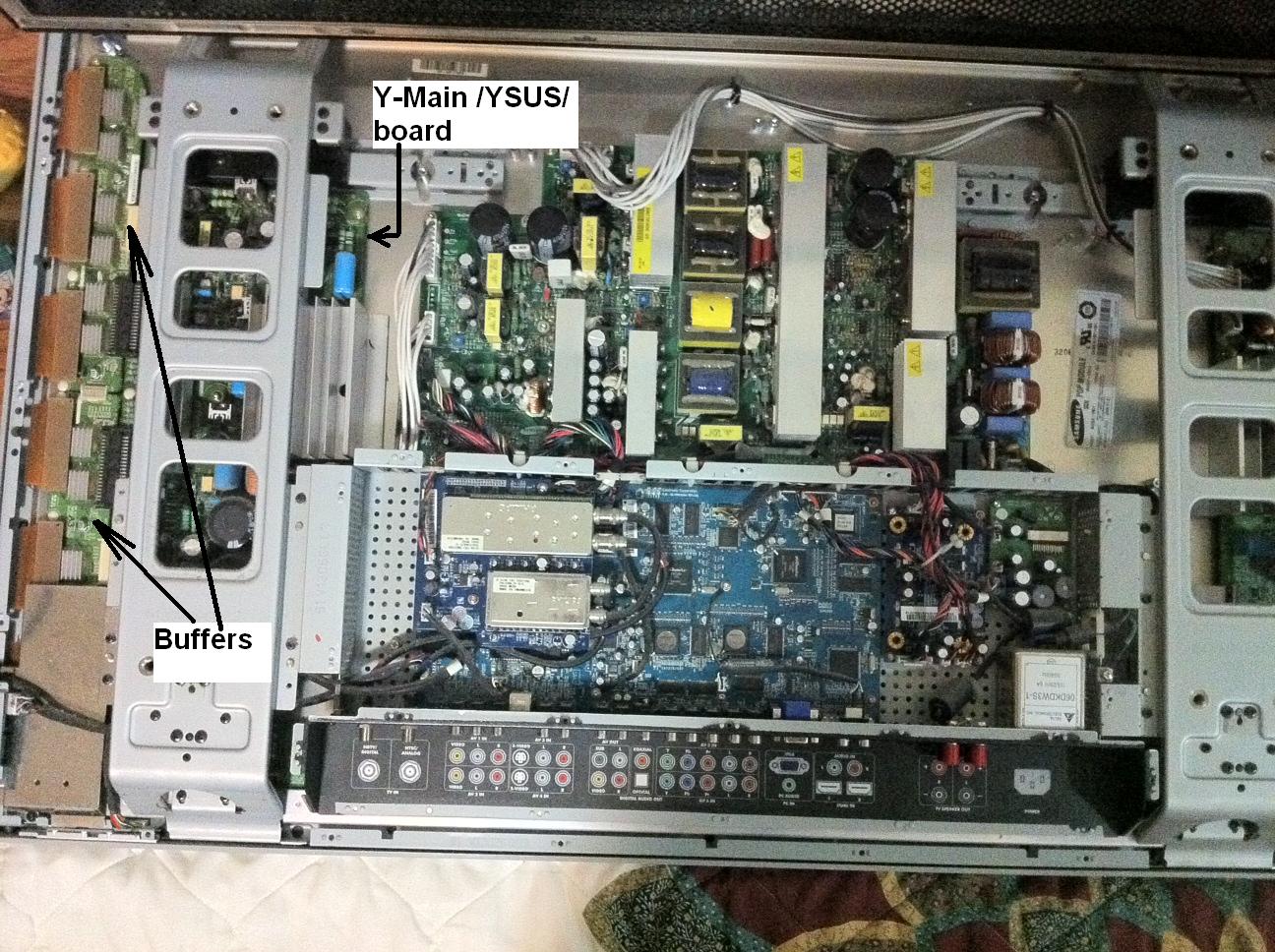
It features the infamous trio of 1) Y sustain board LJ92-01200A / LJ41-02759A and the related two buffer boards 2) LJ41-02760A / LJ92-01202 and 3) LJ41-02761A / LJ92-01203.

This trio on its own is a source of a bunch of problems that I had touched on in previous posts and will soon summarize and expand in a new larger post.

All TVs (and there are quite a few of them) using the same trio exhibit the same symptoms, regardless of their brand. Again, that is discussed separately.


This post focuses on a specific problem commonly observed in DELL W4210C HD plasma TV and other TVs that use the same power board, specifically the PSPF651B01A /  LJ44-00110A.

Symptom: Upon powering on the TV you can hear the power board starting to work, but screen never comes up. TV may stay on or turn itself off after a short while.

Note: This symptom is very similar to the one exhibited by a dead buffer/sustain board depending on how did they burn (which can't be predicted). It is very important for you to understand that what's described here may be not what you're looking for. But it's sure very common and if it hasn't happened to your TV it will sure happen!

If your TV has been showing pink/red horizontal lines prior to dying, on parts of the screen or on the whole screen, then this post is likely not for you (even though you may still benefit from reading it).

Solution: The power board of the W3201C HD has 2 electrolytic caps that are under-rated and tend to cause problems with the basic power supply needed by the main board. When they dry too much the main board just fails to operate normally and the TV, upon initial power-on hangs in an undefined state where pretty much the only thing you can do is power it back off. Sometimes it powers off by itself after you wait enough.

To get to there you need to lay the TV down on the ground, remove its pedestal / stand and then unscrew all the bolts that hold the back cover to the main chassis. There are two types of such bolts and there are a lot of them. Other than their quantity, though, it shouldn't be hard to do it.

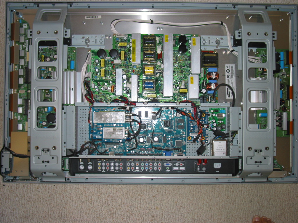
Here is what you will see after you remove the back cover:


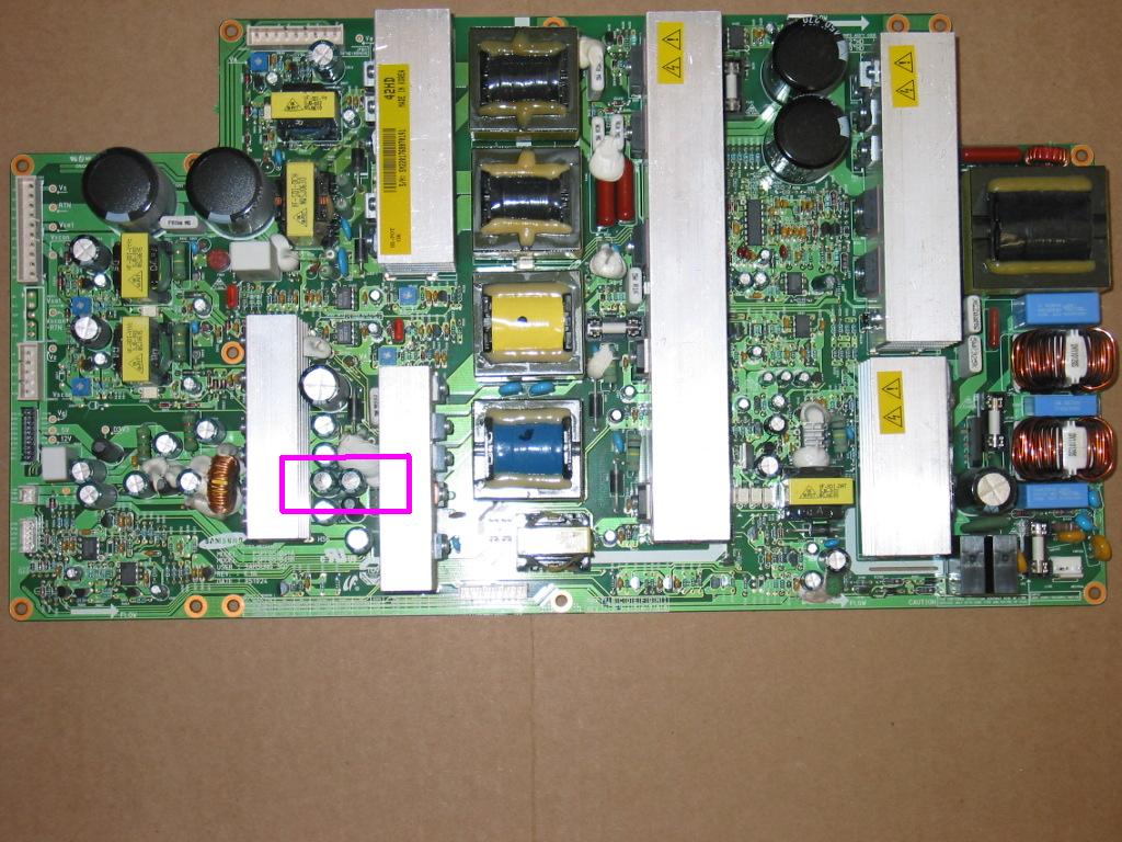
The power board is the large green board with many heat sinks and transformers in the upper half of the TV. You can unplug all connectors (no need to remember which is goes where - can't confuse them) likely except the one in the middle bottom part.
To unplug that one you'll need to carefully unscrew all the bolts holding the board in place and pull the board upwards a bit. I strongly recommend using a magnetic screwdriver so that you don't end up chasing screws around the TV body. This is dangerous and may hurt.

What you're looking for is a pair (or more) of capacitors in the highlighted area that have swollen / bulged tops.

The swollen / bulged capacitors are a common visual, but not ultimate indication of bad caps. If yours aren't bulged they may still be bad and even if they're not we still recommend replacing them because it is only a matter of time before they turn bad unless they have already been replaced with others with higher voltage rating.


We will not put the information for the caps needed here because we know there are technicians monitoring this blog and copying the ideas and know-how from it. Besides, if you get to there you'll know what you're looking for.

At this point you have several possible options:
1) You can identify and find the replacement capacitors needed by yourself. Make sure you get caps that have same capacity as the original, same or (preferably) higher voltage than the original and same or higher maximal operating temperature (105 degrees should be good).

Be advised that space is tight there and it'll be difficult (and more expensive!) to fit in caps with higher voltage rating simply because they will not fit in place.

2) You can save some time and thank us for writing up this blog by purchasing the capacitors from Coppell TV Repair. They'll be shipped within 1 business day via USPS first class mail.

3) If you think you can't do the replacement yourself you can send us the whole power board and we'll do the replacement for you for a very reasonable flat rate. Contact us for details, the first of which is make sure to package the board very well!