Sunday, October 24, 2010

DELL W4201C HD powers on / off no picture - how to fix

This article describes a common problem and fix to all DELL W4201C HD plasma TVs. We've done enough such fixes to realize this is a serial defect that is going to be present in most if not all of these TVs.

5 May 2011 update: The same symptoms and solution apply to DELL W3201C, DELL W5001C and DELL W4201C!


You will benefit from doing it even if the actual problem with the TV turns out to be different (which is always possible).

If you can't do this on your own you can send the power board to Coppell TV Repair and we will do it for you for a very reasonable fee.
(or you can send it to one of the other technicians who read this blog, educate themselves and start offering the same service; we can name a few.)

Anyway, let us start with saying that the DELL W4201C is a Samsung plasma TV sold under the DELL brand.

It features the infamous trio of 1) Y sustain board LJ92-01200A / LJ41-02759A and the related two buffer boards 2) LJ41-02760A / LJ92-01202 and 3) LJ41-02761A / LJ92-01203.

This trio on its own is a source of a bunch of problems that I had touched on in previous posts and will soon summarize and expand in a new larger post.

All TVs (and there are quite a few of them) using the same trio exhibit the same symptoms, regardless of their brand. Again, that is discussed separately.


This post focuses on a specific problem commonly observed in DELL W4210C HD plasma TV and other TVs that use the same power board, specifically the PSPF651B01A /  LJ44-00110A.

Symptom: Upon powering on the TV you can hear the power board starting to work, but screen never comes up. TV may stay on or turn itself off after a short while.

Note: This symptom is very similar to the one exhibited by a dead buffer/sustain board depending on how did they burn (which can't be predicted). It is very important for you to understand that what's described here may be not what you're looking for. But it's sure very common and if it hasn't happened to your TV it will sure happen!

If your TV has been showing pink/red horizontal lines prior to dying, on parts of the screen or on the whole screen, then this post is likely not for you (even though you may still benefit from reading it).

Solution: The power board of the W3201C HD has 2 electrolytic caps that are under-rated and tend to cause problems with the basic power supply needed by the main board. When they dry too much the main board just fails to operate normally and the TV, upon initial power-on hangs in an undefined state where pretty much the only thing you can do is power it back off. Sometimes it powers off by itself after you wait enough.

To get to there you need to lay the TV down on the ground, remove its pedestal / stand and then unscrew all the bolts that hold the back cover to the main chassis. There are two types of such bolts and there are a lot of them. Other than their quantity, though, it shouldn't be hard to do it.

Here is what you will see after you remove the back cover:
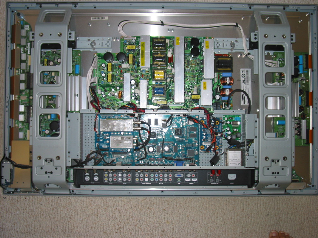


The power board is the large green board with many heat sinks and transformers in the upper half of the TV. You can unplug all connectors (no need to remember which is goes where - can't confuse them) likely except the one in the middle bottom part.
To unplug that one you'll need to carefully unscrew all the bolts holding the board in place and pull the board upwards a bit. I strongly recommend using a magnetic screwdriver so that you don't end up chasing screws around the TV body. This is dangerous and may hurt.
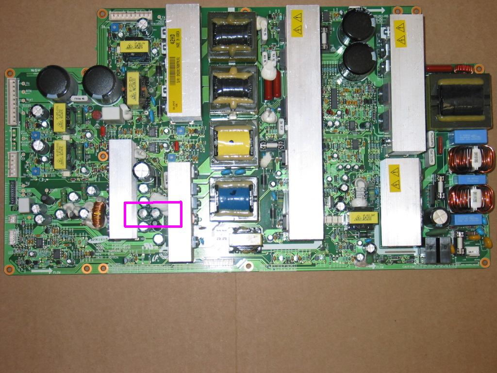
What you're looking for is a pair (or more) of capacitors in the highlighted area that have swollen / bulged tops.

The swollen / bulged capacitors are a common visual, but not ultimate indication of bad caps. If yours aren't bulged they may still be bad and even if they're not we still recommend replacing them because it is only a matter of time before they turn bad unless they have already been replaced with others with higher voltage rating.


We will not put the information for the caps needed here because we know there are technicians monitoring this blog and copying the ideas and know-how from it. Besides, if you get to there you'll know what you're looking for.

At this point you have several possible options:
1) You can identify and find the replacement capacitors needed by yourself. Make sure you get caps that have same capacity as the original, same or (preferably) higher voltage than the original and same or higher maximal operating temperature (105 degrees should be good).

Be advised that space is tight there and it'll be difficult (and more expensive!) to fit in caps with higher voltage rating simply because they will not fit in place.

2) You can save some time and thank us for writing up this blog by purchasing the capacitors from Coppell TV Repair. They'll be shipped within 1 business day via USPS first class mail.

3) If you think you can't do the replacement yourself you can send us the whole power board and we'll do the replacement for you for a very reasonable flat rate. Contact us for details, the first of which is make sure to package the board very well!

Wednesday, October 20, 2010

Note to all customers requesting exchange before their board has arrived for service

It is hard to please everyone.

Wait, I take that back.

It is impossible to please everyone.

Customers who send in boards for repair frequently email us after purchase asking that we send them already serviced boards back before their arrive. Some of them want it because they want to watch the Sunday game others want it because they have customers on their own who want to watch the Sunday game.

But there's also a third kind : those who want to get rid of their trashed board and want to get a replacement before we see that it's been trashed.

This week alone I had to deal with two of these. It takes a lot of time, it is annoying and it inevitably results in recording a loss - financial and emotional.

I am not making this up. Currently there is a case escalated to eBay to resolve a claim by user aguilar35domingo against CoppellTVRepair because we did not sent them a different board than the one that they sent. It was the dirtiest board I have ever seen and if there is anything that I am sorry for it is that I took the challenge and restored it in the first place. So after restoring it, testing it and sending it back, CoppellTVRepair received positive feedback and then - guess what - an open case.

And yesterday another claim was opened by user jgul1717 complaining he hasn't received a board just yet when his own was on its way. Today the board arrived and I may post a picture of it later on, even though I am not sure I'll be able to catch what is needed. Long story short, someone with a VERY BIG and VERY HOT solder iron has re-soldered most joints under the board, resulting in a complete mess and several burned tracks.

Those are two cases which - for the time being - Bay counts against our TopRated rating even though we have made it very clear in the listings (and it is very untuitive) that we are not wiling to exchange good serviced boards for tempered ones.

Also this week a customer from Jersey asked that I send him a board in advance. We have spoken on the phone earlier in the week and I stated our policy, but he kept on pressing so I eventually said "OK, send me a tracking number and I'll see what I can do". I know I said that because I was very clearly aware I did not want to make a firm promise that I might not be able to fulfil.
Anyway, today customer called and was upset the board wasn't yet sent. Truth is it wasn't because I had to deal with cases practically identical with his one.

The difference is in the sender - this NJ cusomer is most likely a decent and honest person, maybe just as you are - but the case under which we operate is practically the same.

You see, we can't judge people unless we kno them very well. And, take it from me, even then when money are involved. But that's another story.

What I am trying to say is that when there is uncertainty and very objective considerations in place then the best way to go is to stick by the rules that a deal has been signed over.

That would result in slower, but more reliable business. We may lose the NJ customer because they may feel we did not make an extra leap for them. Even though I had to - and did - rush today to get the cutoff time for UPS to send their particular board so that it leaves today and not tomorrow.

If that's the way then so be it. We'll fulful the deal arrangement at least as good as it was listed and if you are unhappy then please refrain from doing a business with us for the future.

If you've already placed an order call us and if possible we will stop it and refund you.

To some long-time customers we will make exceptions, of course. And assume the risk.
Please do not be offended if  you are not considered a long time customer on your second order.
It is exceptions we are talking about here, not rules for long-time customers.

One popular and simple approach to receiving a board in advance is to pay a purchase (and not service) price for a board, then send the core in and receive credit when it arrives and passes inspection that it hasn't been tempered with.

We did that a few times and haven't had problems this far. I'd be interested to hear if you like the approach, but I can immediately point a few drawbacks:
- it requires supply of cores that can be serviced and turned into boards to sell. Not everyone will be sending in their core and not every returned core will pass the inspection
- selling full price board has disadvantages for placing in search engines

In conclusion...we are here to help you, our customer.
And even though it may seem contrary at first, keeping the rules that build the foundation of the business is more important than groing the business.

Saturday, October 16, 2010

Vertical lines / vertical strip in LG 50PC3D, 50PX1D, 50PC1DR, Vizio P50HDM, P50HDTV20A and others - defective YSUS buffers 6870QDC004A and 6870QDC005A


This article applies to a wide number of 50'' plasma TVs utilizing LG plasma panels and sustain boards like 6871QDH088A / 6870QYC004A , 6871QYH039B, 6871QZH044B, 6871QDH089A / 6870QYC104A and the likes.

In fact, many of what is said here applies to pretty much all plasma TVs made as of 2011. The principles are the same and you can easily transfer the knowledge applied here to a different model.

We at Coppell TV Repair service a lot of plasma sustain and buffer boards.

In my opinion there is a lot to be said about servicing them properly (as I have mentioned in a previous article), but today I want to focus on the 6870QDC004A and 6870QDC005A and one of the most common issues we see with them and the different TVs in which they are used.

Buffer board(s) sit on the left side of the main Y sustain board, which sits on the left side of the TV if you look from the back.

In our case there are two buffers, called upper and lower buffer, responsible respectively for setting the line pixels in the upper and lower half of the display.

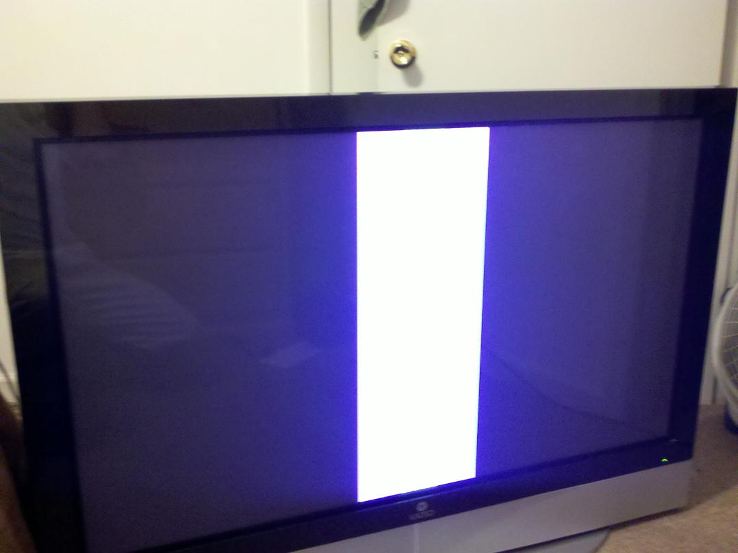
Sometimes we receive calls from angry customers who, after installing the Y or even Z sustain boards that we return after service, find out that the TV screen is nothing but a strip of one or more vertical lines. Like this:


Or, if a signal is present to the TV, like this:


"Your board does not work", they proclaim, "and I want to know what do you intend to do about it!"

I wish we could really do something particular about it!
If I had the power I'd turn those customers to exclamation marks right on the spot!

Long story short, this is a typical result when a buffer board has failed.

Once - out of easily hundreds of times - I have seen the same thing caused by a bad YSUS board. It was caused by a filter capacitor at the YSUS output which has decided to short, but not quite completely, so board was running, but severely disturbed.

Easily 99% of the time when you have vertical bars on the screen it'll be a buffer board.


If there are two it could be either of them.

Now here's how to test them:

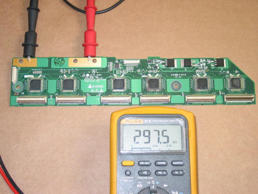
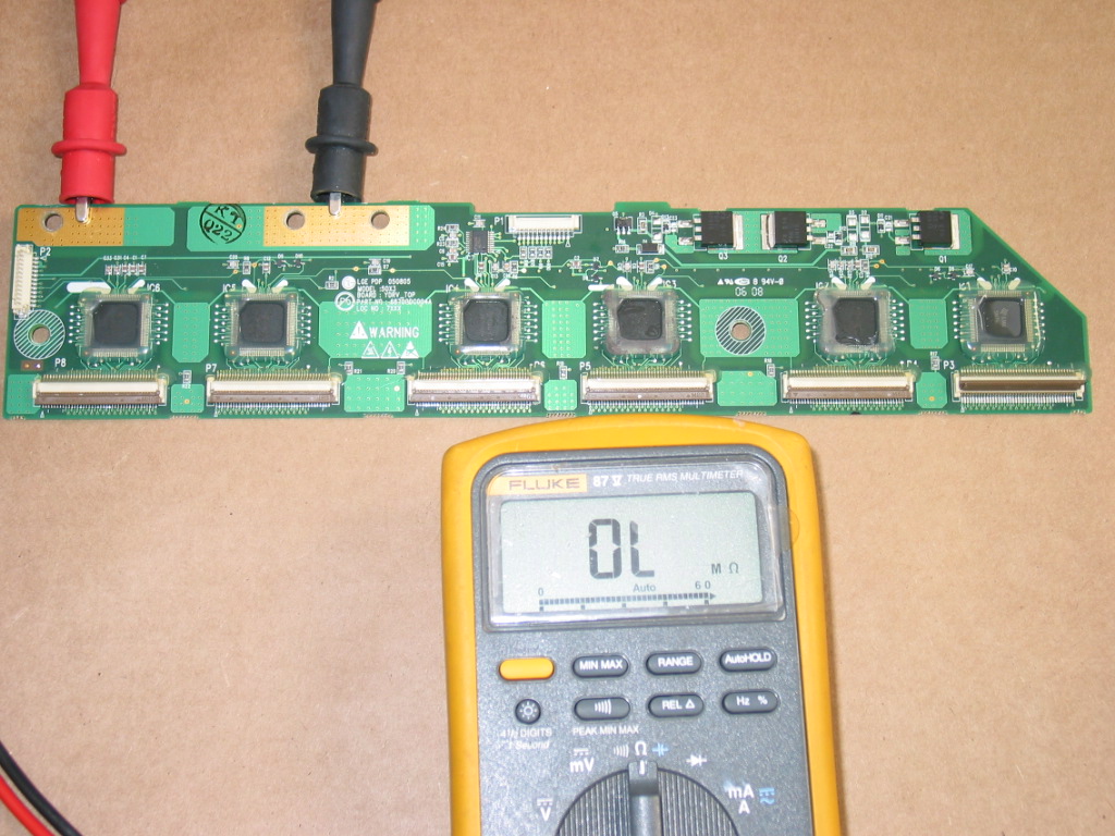
Probably the easiest check you can do on the boards is between the floating ground and the high voltage copper pads that contact with the Y sustain board.
A good board will have around 300 to 600 kOhm resistance one way and infinite in the other (using diode test mode):


A bad board, would typically have resistance in both directions and most of the boards that I have seen measure hundreds of Ohms in one of the directions. That's a clear sign for a bad board.

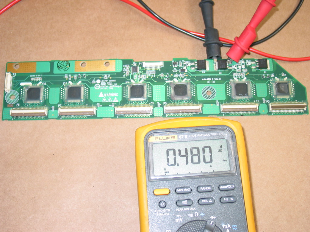
Another quick test that you can run which might want to try is checking the power FETs on the board for shorts. You can measure just one and any one of them because all three are in parallel.


What you are looking for is a standard FET test condition - diode-like effect with sufficiently high resistance in either direction. Now pay attention here that sometimes you may get a false positive: depending on the unit you have and its algorithm for detecting shots, many devices (including my Fluke!) are often signaling short when , in fact, there isn't any. It's likely the built-in protection diodes in the transistor that cause the effect, I am not sure about it, but I have more than certainly observed it in different kinds of FETs including those on the buffer boards.

The way I eliminate the false positives is as follows: first, try it both directions. If it's really short it can't be uni-directional.
Second, after testing in diode mode, switch to ohm-meter and test it there as well. The ohm-metter algorithm is different and usually doesn't trigger.

WHAT TO DO?
Usually only one of the buffers burns at a time and does not affect other boards in the TV.
It's OK to replace or repair only that buffer.

As of the date of this writing a replacement used buffer can be found for about $35-$40 delivered to you. Sure time will change that, but not very clear in which direction.

Just make sure you buy from someone reliable who will either sell you a buffer they know is good (by reading this) or ready to offer you warranty about it.

Someone like Coppell TV Repair :-)

So here are your options:

1) Seek to replace the burned FET (or better, yet, all three FETs) on the board
  • Check Coppell TV Repair store for 6871QDH088A / 6871QDH089 repair kit

    Note all three FETs are connected in parallel and you can't tell which one is shorted until you actually fetch it and try it individually.

    I should also mention that the Fluke I use is sometimes tricked by the FETs and led to believe they are short when they aren't. I test in diode mode and am used to checking for continuity in each direction at least two times before taking off a component.

    Before you buy the kit you may also want to be sure that you do not have a burned IC on the board. Repeat the test described above AFTER you remove the suspected FET. You may even want to remove all 3 FETs (and then replace all three of them) to see if the resistance measured will restore.

    If it doesn't then you have a burned IC in addition to a burned FET.

2) Replace the whole buffer board


3) Replace burned ICs on the board
  • Check Coppell TV Repair store for SN755866 plasma output register IC

    I would not recommend that for someone who hasn't tried a few times.

    If you are dying to get into it that's OK, but consider the high probability of having a few failures before you start doing it right.

    The proper replacement of TQFP-64 and TQFP-100 ICs is beyond the scope of this article.

Tuesday, October 12, 2010

Fix for furnace fan not blowing, Carrier 350MAV 58MSA with 325878-751 / HK42FZ009 HK42FZ008

If I haven't been posting lots of TV repair hints lately it's because I've been busy fixing TVs or cars or , as of the last two days, HVACs.

As Terry Pratchett puts in in one of his brilliant books, the price for being the best is that you have to be the best. Modesty is behind getting the job done. (that is from me, not Terry Pratchett)

OK, down to business. Based on what I found I expect this to be a common problem with Carrier home AC systems and I hope this will help others in my position save time and money.

Problem likely affects all Carrier furnace located control boards 325878-751 - models HK42FZ004, HK42FZ007, HK42FZ008, HK42FZ009, HK42FZ011, HK42FZ016.

Those are used in HVAC system models 340MAV, 345MAV, 350MAV, 351DA, 373LAV, 376CAV, 383KAV, 393AAV, 395CAV, 480BAV, 481BAV, 490AAV, 58MCA, 58MSA, 58MXA, 58PAV, 58RAV, 58WAV, 58YAV, 58ZAV, GB1AAV, GB3AAV, PG8DAA, PG8UAA and PG9MAA.


I'll first give you the very short version and then the longer one with pictorial.

SHORT VERSION
Symptom: AC control panel is on, says "COOL ON" but no air blows anywhere in the house. Same with FAN ON. Outside unit (compressor) works when the "COOL ON" is displayed on the control panel (it is normal for it to NOT work otherwise).

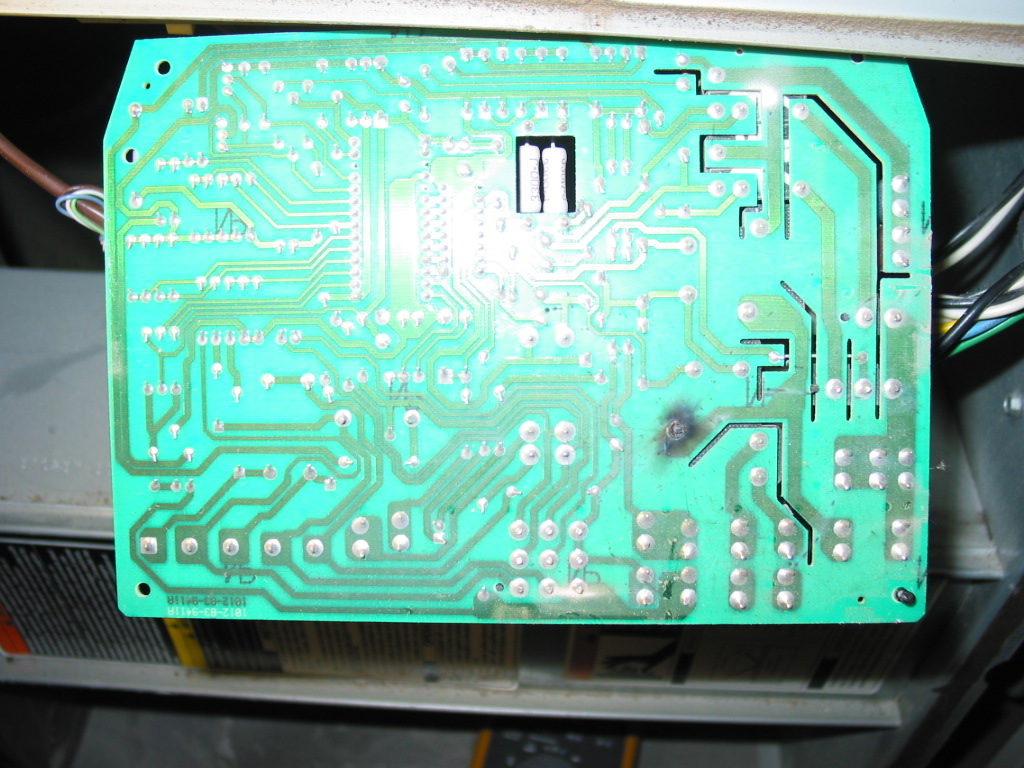
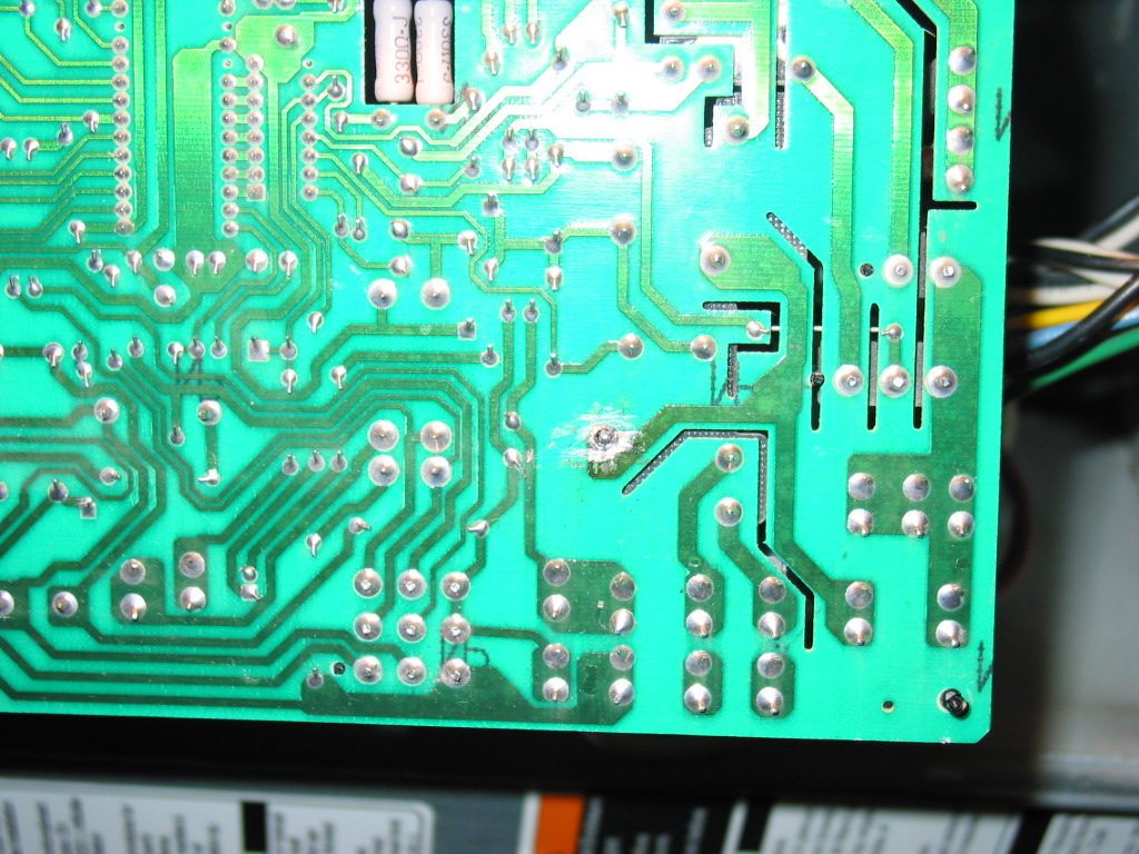
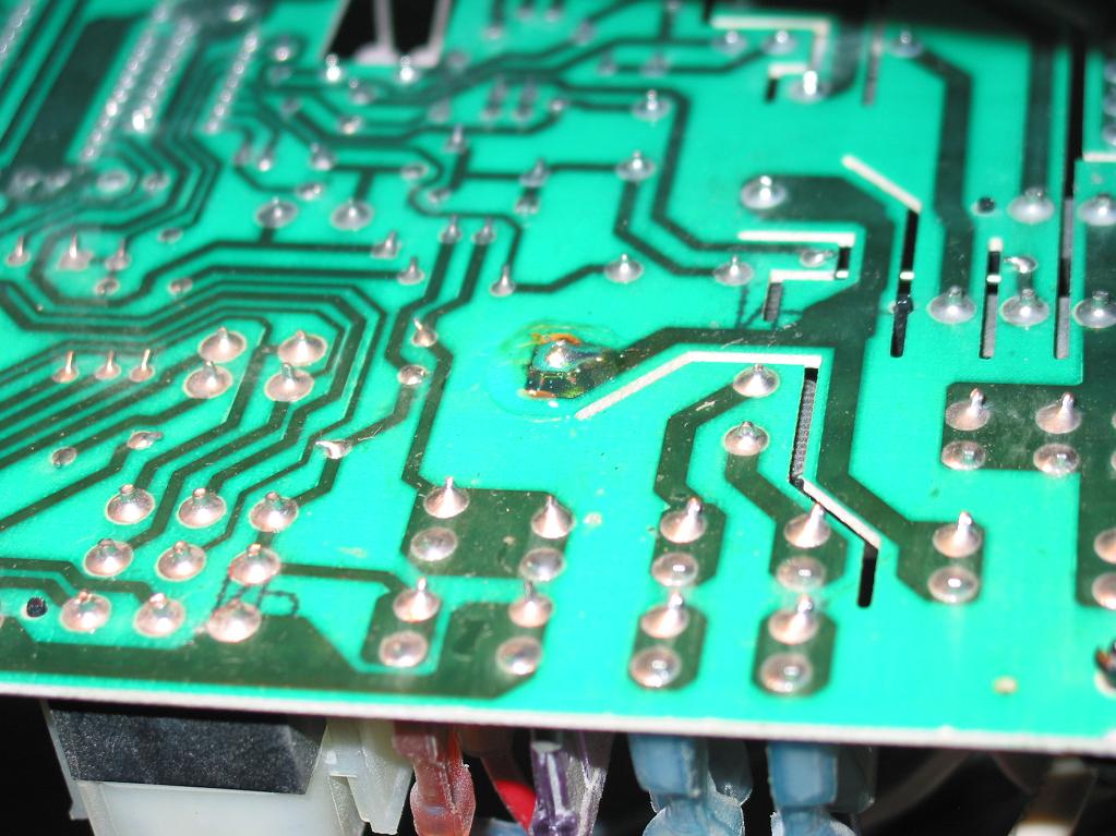
Problem: Burned relay solder contact on control board 325878-751.
(of course the same symptom may be caused by other problems; this is the problem that I had!)

Resolution: Clean and re-solder the contact, cover with protective coating to prevent from happening again.

LONG VERSION

So the AC turns on (cold in my case) but no air flows anywhere in the house. As with everything I started on Internet and first read this article. You may read it as well, it's a simple and useful introduction.
I tried what was suggested there - resetting the system once - before you try other things, because I remember one time in the past when I paid AC technician $100 to do just that - reset the unit. Nor do you want to try to fix something that isn't broken in the first place...so try soft reset first!

Once I established the outside AC works and the blower doesn't - even after reset - I took a closer look at the furnace. Here is what I saw:


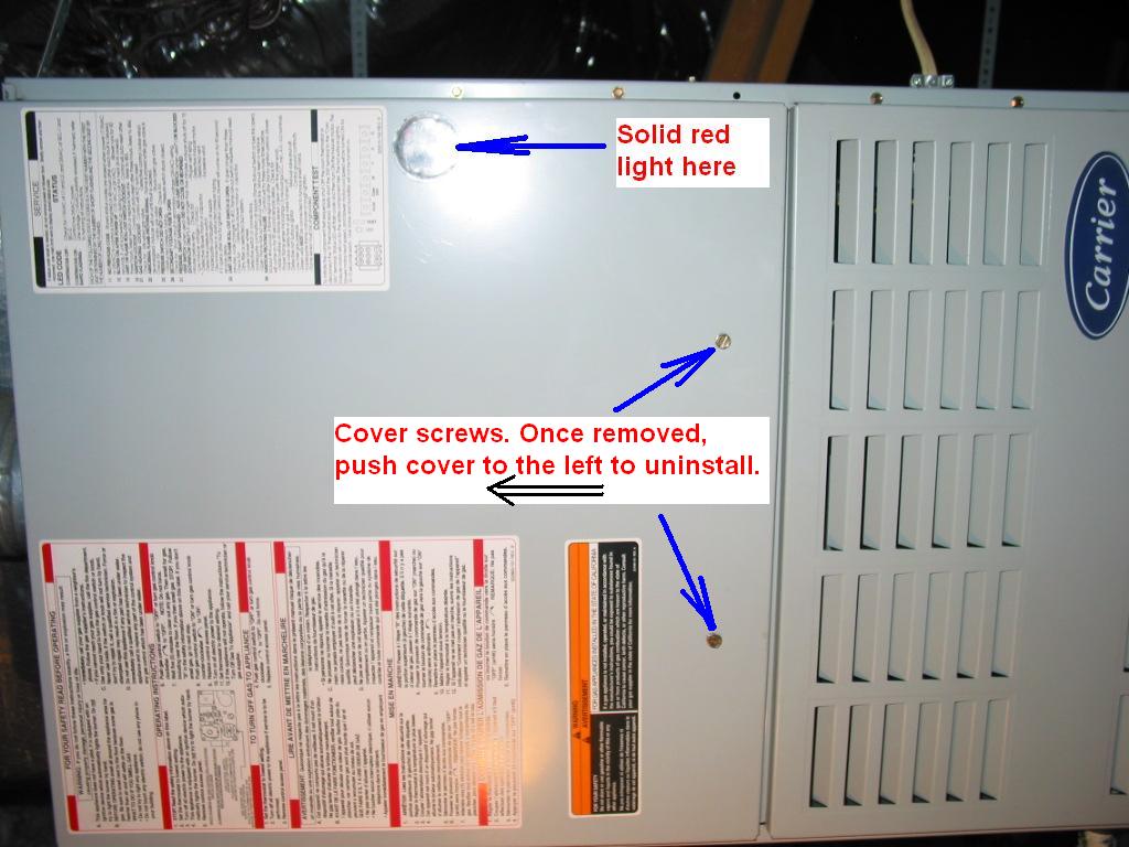
Notice the LED light was solid red, indicating presence of 24V to the system and no errors.

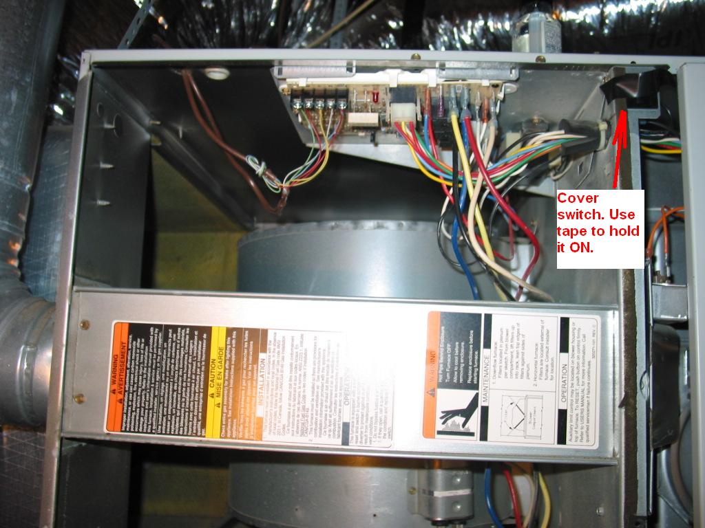
I took the cover off::

The cover switch at the upper right corner is used to automatically turn off the control board whenever the cover is taken out. You will need to use a tape to stick it in closed position and run tests, but remember that any later operations on the board better be done with the whole system turned off by this AND the main unit power switch (follow the furnace power cable to the switch).

One thing you will want to do is bring light up there in the attic as I did. Helps tremendously and pays the effort of doing it in the first minute you have it!

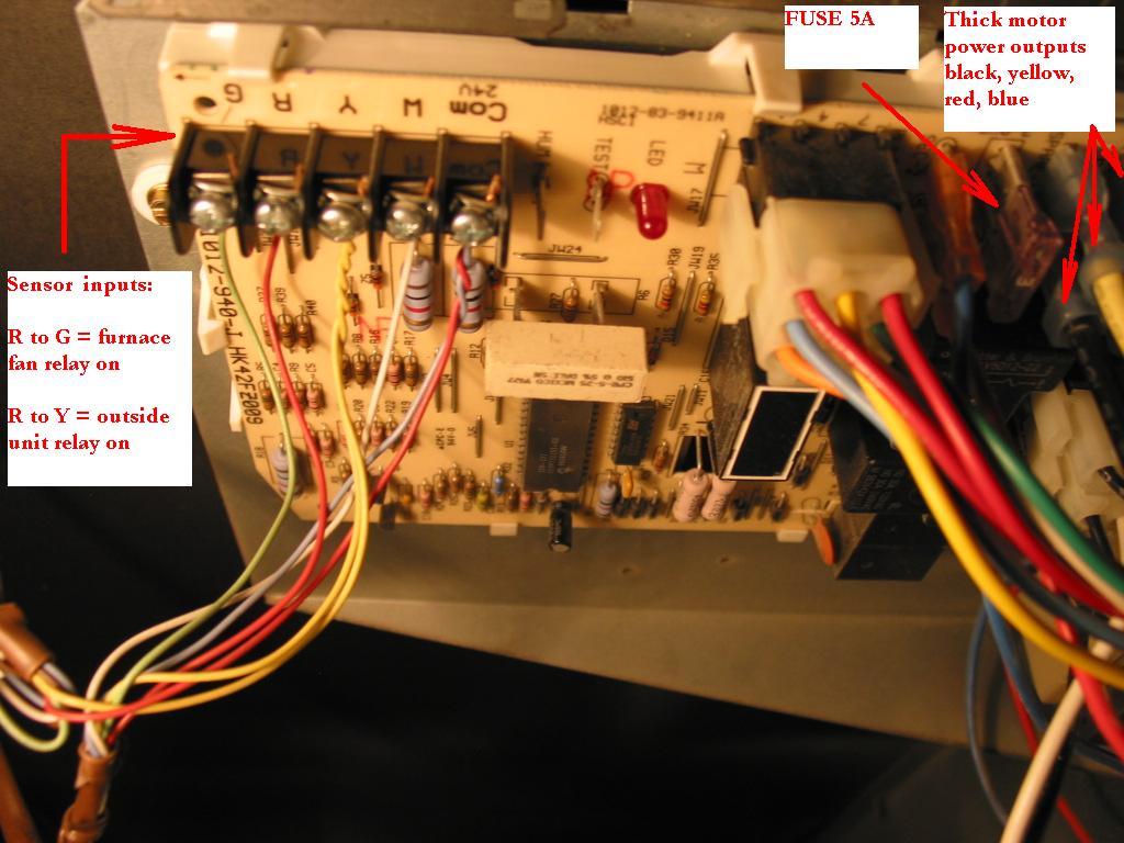
Let's take a closer look at the board:

On the left side you have the control/sensor connectors marked G, R, Y and W for the color of the wires that go to them. Last is the COM.

Also on this picture I am showing the board's fuse, which is worth checking before you do anything else. I mean that's what fuses are for, right?

Finally, you can look at the thick cables that go from the board to the motor. There are several of them because there are several different windings for different speeds of the motor. Only one of them is being active at a time though and they take simple 110V AC. There's a fifth (white) cable not shown in the picture, which is the common second connector.

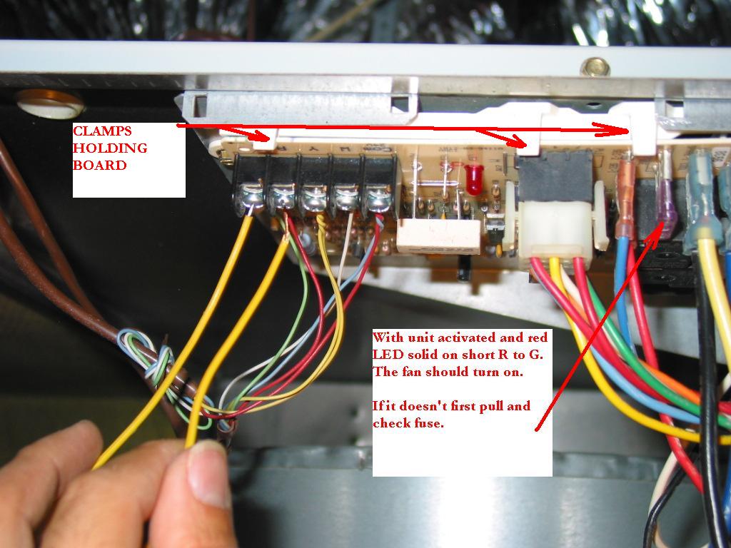
Now, to test the fan you should tell the board to close the relay that supplies it with power. You do that by shorting G and R on the board (the door switch must be taped in and LED must be solid red when you do it):
 You should hear a relay click quickly followed by the noise of the motor in the back.

In my case, I could hear the click, but the motor never did a spin.

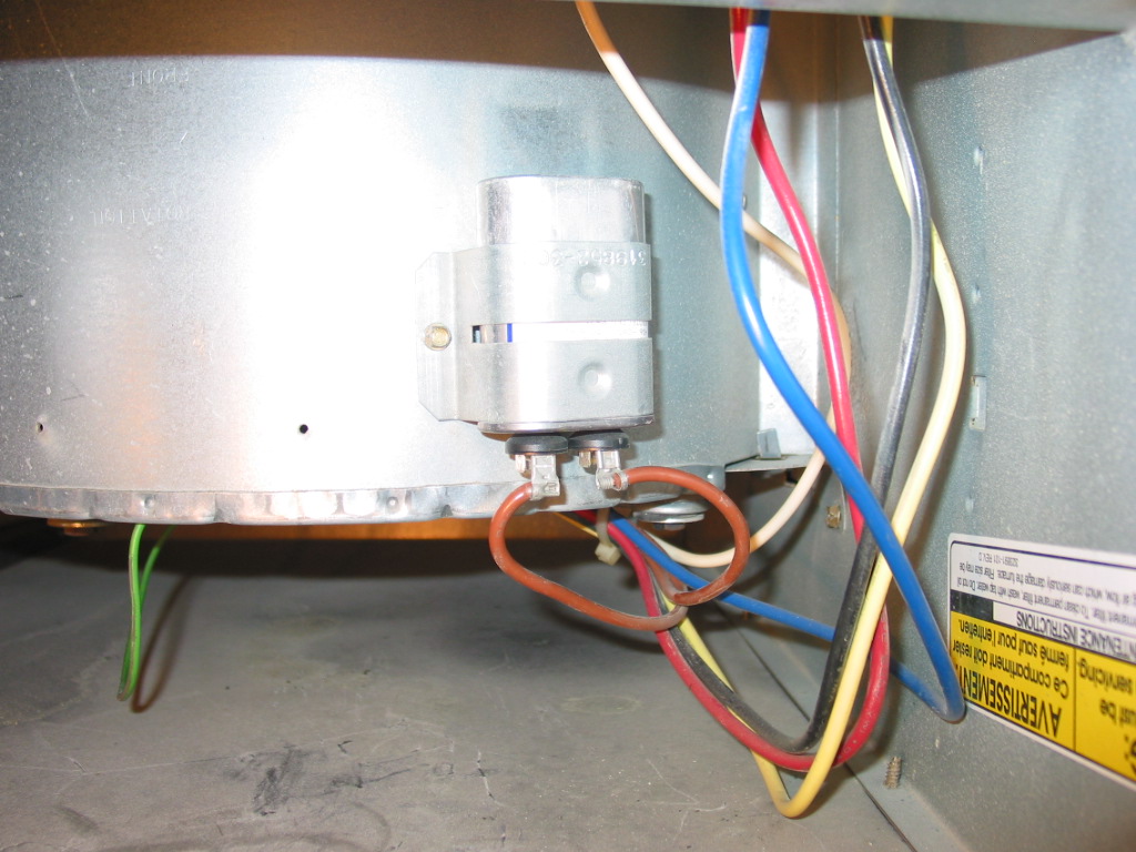
Now, from what I learned on Internet and what I first checked, one equally common problem that shows same symptoms is failed start capacitor on the motor. The start capacitor is located on the motor itself and looks like this:

Before doing what I describe below I actually took it out and measured it with my FLUKE. It measured what it said on the unit itself - around 10 uF, but bear in mind this is not always reliable, even with a Fluke...not to mention many of you may not have Fluke. At the end of the post I give a few useful links from pros in this business that helped me and may as well help you.

I returned the capacitor in place and I was planning on directly passing 110V to the motor to test if it will spin when I decided to first take a look at the board due to something I had read about repeatedly failed solder joint. I have seen the exact same things in other power appliances such as laser printers and some large TVs and I figured it's easier to check this than trying 110V on a motor I have never seen before.

So after disconnecting the furnace from the master switch, I released the board clamps (see the above pictures) and gently pulled the board out. There was actually one black clamp different from the others. It was was holding the board stuck to the underlying (or, since it is upside down, above-lying) plastic base.
This clamp is located at the front right side of the board and I just gently pried it out with a large screwdriver. May not be the best way to do it, but worked for me and it should for you as long as you do not apply too much power.

Once I pulled the board out I could immediately see the problem:

From here on it was very easy. Just clean with a small screwdriver or a knife, solder (with flux!) and, in my case, apply acrylic conformal coating on top of the solder to decrease chances from this happening again.
The next two pictures aren't too good to show that, but I'll add them anyway. I know Megan Fox is unlikely to ever pick me as a lead photographer for her photo sessions and if I can live with it so should you :)


ADDITIONAL INFORMATION:
I thank to the people who had posted information that helped me solve this problem without paying any extra money. The very least I can do to honer their work is to point you to it:

1)
http://www.askmehelpdesk.com/heating-air-conditioning/c-heat-does-not-work-w-thermostat-set-auto-77039.html

2) http://toad.net/~jsmeenen/motor.html
 

Wednesday, September 29, 2010

LG 50PC3D with negative image on screen after replacing YPPD-J015C on 6870QYC104C

Yesterday an email from a customer arrived and it said:: 

Dear Coppell TV Repair,
we purchased part # YPPD-J015B from your company through PayPal.
The item arrived and is defective.  Please advise how we may return this part to you for exchange or refund. 

Thank you.

Since we sell J015C and not J15B and since the mix-up of a J015C and J016B is deadly, my first guess was that they had installed J015C as a replacement of J015B and, sure enough, it would have lasted a very short time.
I wrote back explaining that we pay premium for our J015C components (and we really do!) and that we haven't had a defective one in a very long time (and indeed we haven't!) and that perhaps they confused J015B with J015C. This is a common mistake which is the reason why in the listing for the YPPD-J015C sale we have multiple warnings about the need to use C versions for both IPM modules on the sustain board.

Here's the response:
You are most certainly NOT correct in your assumptions.  The part you sent us was NOT NEW. As soon as we received it my technician pointed out that there were imprints from the screws where it was formerly fitted and pinholes on the back of the silicone seal.
I told him to go ahead and use it because we had previously bought parts from your company with no problems.
The TV did not fail as you presume but has a negative video.
I do not dispute the experience of your company or the satisfaction of your clients.  In the pas I was also a satisfied client.  However, I resent your implications that we dot not know what we are doing here. we have been successfully servicing TV's here for the past 22 years and like Coppell TV we are highly trusted and respected.
I am telling you that the part you sold us is defective and would like your cooperation to return it for exchange or refund.
Now, I am posting the response without any changes. This way you can see that someone with 22 years of experience (and, frankly, that's more than  us!) claims the part we sold them was used and defective.
 You draw your conclusions and decide if you want to purchase from us. You were warned!

For the curious minds I'd like to point out that the sustain IPMs are NOT involved in forming the color of the picture on the display. They are responsible for the high-voltage impulses that power each individual row on the plasma, but NOT with the color.
Any defect in the sustain IPM will affect typically the brightness of the entire row, in fact the entire screen.

Other parts on the board, however - and they are, of course, related to the IPM - are responsible for using the color information to 1) control the IPM timing and 2) dispatch that information to the sustain buffers.

At the moment I will not say which are those components. I will only say that they go bad often when J015C shorts and need to be checked when J015C is replaced. (BTW this also confirms customer was right about my initial guess being incorrect; they had clearly used J015C and they had observed a common problem with a failed J015C).

What has happened at the end? Well they asked for a refund or replacement and they got a refund since a replacement would not have had an effect. Since they've been in the business for 22 years and they knew the part was defective (and we knew it wasn't) we kindly asked them to send it back. In order to avoid similar conversations in future we asked them to use a different vendor. As I said we pay top dollars for those parts and believe it or not there's a shortage of components - even at the high prices we pay - and a great supply of customers.

We also predicted they will observe the same result with the next IC they use.

Now that I think about it, we didn't play it in the best possible way. We weren't quite service-oriented and instead of helping them solve their actual problem we got ambitious of proving they weren't right.

Then again what was their actual problem? It depends on where you look at it.

To me it all started with "The item arrived and is defective."
Here's my two cents: if you're a customer and you buy from supposedly respectable source (e.g. top-rated seller with a long history and lots of positive reviews) do not jump to conclusions if things don't go as you expect. 

Try "I am having a problem, can you help me please?".

I'll be the first to admit the advice applies at 100% for yours truly.

Follow-up on October 6 2010: The J015C unit did arrive last night. I was impatient to test so I stayed late , put it on a board and, sure enough, it was working. So much for jumping into conclusions!

Thursday, September 16, 2010

How to test power supply R0804-0901 from Polaroid FLM-3232 / Polaroid FLM-323B

Since we repair those power supplies (contact us for repair if you need yours repaired!) I am often asked how can it be tested if it works.

"My Polaroid just died and after some research I found that it's usually the power supply and then I found your blog and learned that CoppellTVRepair repairs it. I opened up the TV, looked at the board and I indeed have R0804-0901. There are no swollen caps or broken elements that I see...I want to use your service, but I want to know I actually need it before I pay."

That's a fair statement. To start with, only about half the time it's the power supply that goes bad. The other half it's the main board and , at least for the time being, we can't help with that...with more than the helpful information I already posted a while ago about cross-referencing main boards from Polaroid and Memorex.

So it makes a lot of sense to test the power board instead of assuming it is dead.

And here is how:

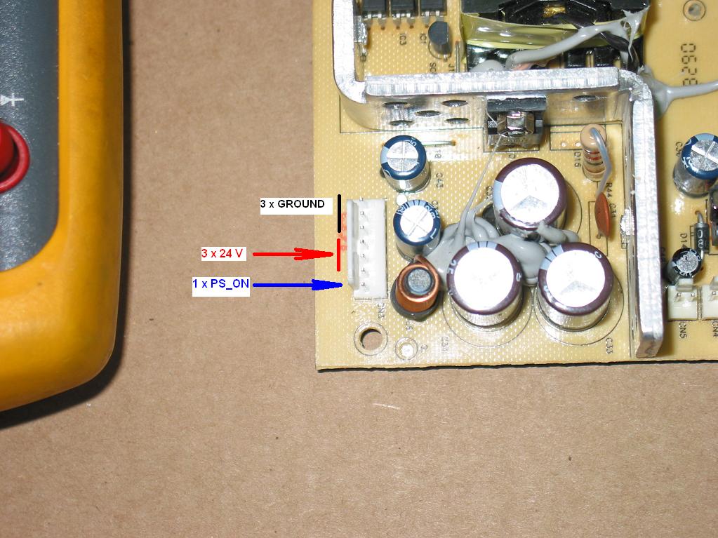
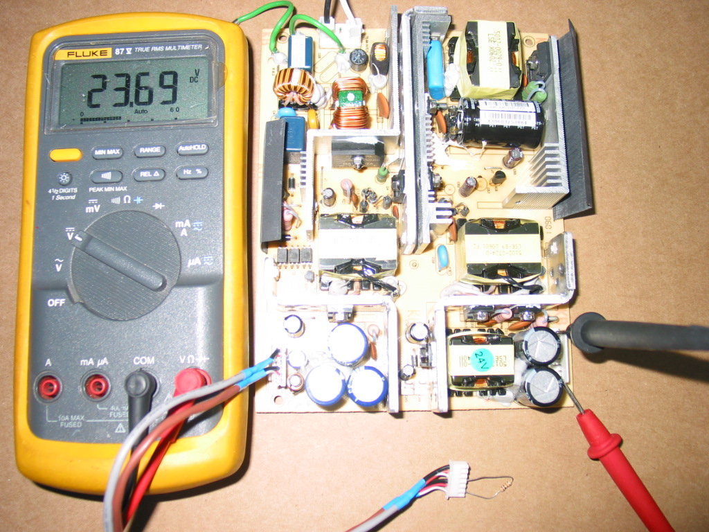
The R0804-0901 is extremely simple in regards to operation and outputs. Unlike most TV power supplies its only standby circuit produces 24V and those can be measured at any time - on or off - at connector CN3, where the first three pins are ground, the second three are +24V and the last one is used to turn on the secondary power source for the back lights:


I measure the voltage by simply feeding power to the supply and sticking the meter probes in the connector:

Most of the time, if you have 24 volts there, your power supply is good.

Now if you want to be sure that everything works, then you also need to test the secondary output, which is at connector CN2 across the board.
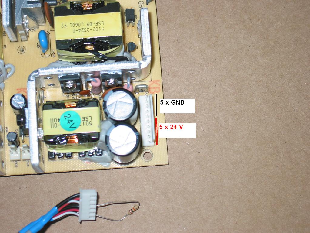
It is even simpler as it has 5 pins ground and 5 pins 24 volts (separate from the first ones!):

In order to do that, though, you need to turn that circuit on, which is done by connecting the PS_ON pin on the first connector (look above) to the primary +24V through a resistor. 
Anywhere 1 kOhm to 10 kOhm should do.

On the picture below I had used a simple cable from another TV to allow me to easily connect the lowest pin to some of the ones above it through a resistor.
You will likely not have such a cable handy...but then again you only care about this test if your TV powers on and off, has sound, but there is no back light.

Monday, September 13, 2010

Samsung LN-S4041D LNS4041D shuts down intermittently

Well I'm back from Europe and overloaded with work!

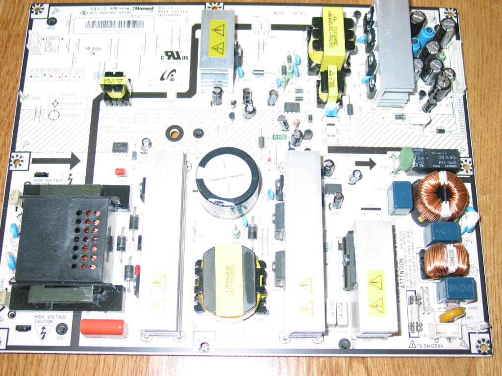
This post is for a trivial problem with the BN44-00134A power supply used in some Samsung LCD TVs.

Just yesterday came across a LN-S4041D TV unit. It was brought in for service with complains for intermittent shutdowns after working for a while.

Sounds familiar - many TVs would do that, very often due to puffed capacitors in their power supply boards.
(of course it is not always the case; remember, nothing is ever certain, so the next time you call a service technician please spare their day and tell them the problem you see and not what you think is causing it!)

So anyway, after taking the back off and looking at the power board this is what I saw:


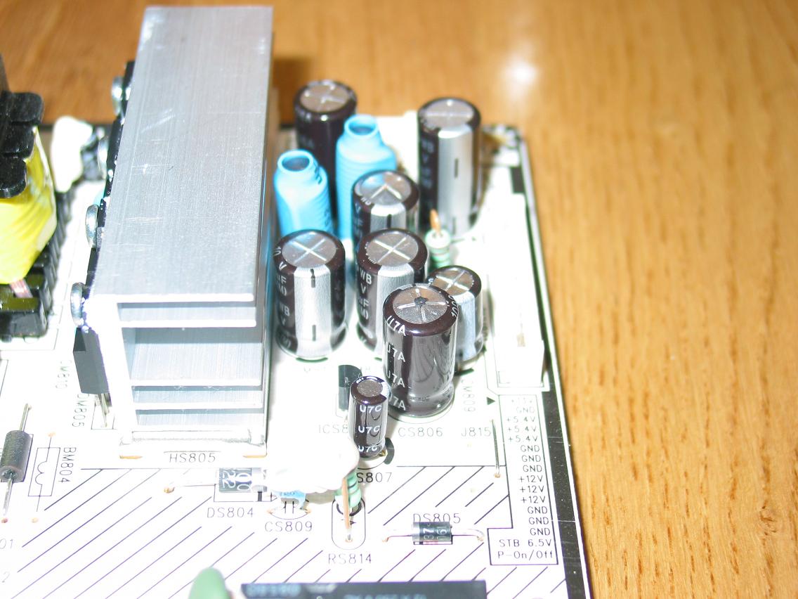
An even closer look at the upper right corner revealed the following:

Did you notice the two puffed caps? They are a little harder to see on the image - I am an electronics and software engineer, after all, not a photographer - but if you know they are there you will see them even on this image.

Puffed caps like that are usually connected in parallel and usually have the same value.

In this case they were both 1000 uF / 10V .

When replacing puffed caps it is usually best to use the same value for their capacity (1000 uF in this case) and always safer to use same or, better yet, higher value for their rated voltage.

Another important property of the electrolytic capacitors is the upper temperature range they can work on. On most boards these days this is 105 degrees Celsius and I recommend using the same or higher value.

Replacing those two with a pair of 1000 uF / 16V / 105 degrees fixes the set and will keep it running for a long long time.

Maybe happily ever after.