Question
I am interested in the following service: REPAIR SERVICE FOR POWER SUPPLY BOARD LG EAY39190301 / PSPU-J702A
With all cables connected, tv flashes 3 blue lights then back to red. With all
cables disconnected, once AC is applied to PB it clicks on then right back off.
If I just disconnect the YSUS, the tv will power on with audio only, no video.
Answer
From the sound of it I would say your power board is working just fine.
As you may know most power supply boards - especially the more powerful ones, which means pretty much all plasma TV power supplies - have several modes of work, most simply categorized by how many circuits are activated to produce output power.
At the bottom is the very low power, always-on standby power supply circuit of +5V or +3.3V.
Then, through a control signal the board is often told to "wake up", which usually involves activation of the power factor correction circuit on the AC side and a bunch of circuits producing bunch of voltages on the secondary side. This is also the stage where the relays click.
And most plasma TVs have yet another stage where the most powerful output voltage - the display sustain one - is being activated and the dreaded Vs is produced.
Power boards have multiple protections built-in in them - the higher the risk - the more and more reliable the protections - and in many cases all you need to find if a plasma power board is faulty is to know if it is capable of producing this last voltage Vs. If it makes it there it's pretty much fine.
And if something gets in the way of producing Vs the power board usually shuts itself down on the way there.
What I am getting at is that the bare symptom that you have a working TV with sound is a very strong indication that your power board EAY39190301 is fine.
And since the sustain board apparently gets in the way of the TV working it's logical to conclude that this is where the problem is.
One more thing on the power boards: some of them - not most, but some - have a programmable ability to turn on all their output circuits when AC is supplied and nothing else is connected to the board.
This is very useful when testing a power board because pretty much all you need to do is pull out all connectors beside the AC power one and supply the AC. If the board clicks on and stays on (and Vs is present, in case of a plasma power supply board) then the board is pretty much fine. Well, apart from load-related or intermittent issues, but both those are fairly rare.
Right now I am not 100% certain if EAY39190301 has such an option and if it does whether it is on or off by default. (if there is, it is always configurable through a controlling pin; it's usually labeled "AUTO").
I am quite certain that your board's cousin (or perhaps brother would be more appropriate) does have such an option and it is ON by default. In other words, when EAY41360901 is supplied with AC and nothing is connected to change the ON signal the board will automatically engage all output circuits and Vs will become immediately available.
Hope this helps!
Sunday, June 9, 2013

Wednesday, May 29, 2013
LJ92-01436A / LJ41-04516A Y-Main sustain post-repair question and answer
Synopsis: Below is a post-repair email exchange we occasionally get after servicing and sending back a plasma TV sustain board to a customer.
I can't say this is very common, but it happens often enough to justify exemplifying it.
Both the question and the answer are valid for any other type of sustain board I know.
Equally importantly, this is a great illustration on why one shouldn't write a nasty and sarcastic note to a service that just sent back a module which didn't make the things work as expected.
Luckily this particular customer wasn't that type, but, no offense meant, enough are.
And it only takes one bad experience to spoil a whole day, sometimes a whole week.
So next time you send us LJ92-01436A / LJ41-04516A Y-Main for repair (or any other module for that matter) and it doesn't work...please do not automatically conclude it is us!
- Bobby
From: the_inxpensive_xperts
To: coppelltvrepair
Subject: Re: Other: the_inxpensive_xperts sent a message about LJ41-04516A Y-MAIN SUSTAIN YSUS REPAIR SERVICE - READ THE LISTING! #160997579922
Sent Date: May-29-13 06:34:04 PDT
Dear coppelltvrepair,
Hey, got the boards, everything looked great, one problem, my screen looks like this, (in the pic), I thought maybe a loose ribbon, but I went back through them and they all were secured. Any ideas as to why it looks like that?

- the_inxpensive_xperts
From: the_inxpensive_xperts
To: coppelltvrepair
Subject: Re: Other: the_inxpensive_xperts sent a message about LJ41-04516A Y-MAIN SUSTAIN YSUS REPAIR SERVICE - READ THE LISTING! #160997579922
Sent Date: May-29-13 07:14:46 PDT
Dear coppelltvrepair,THANK YOU! it was a logic ribbon all buggard up. Fixed now. A little alcohol and a q tip lol. Hooking the HD back up and should be a great picture again. I just ordered the new buffers. Thanks again man.
- the_inxpensive_xperts
I can't say this is very common, but it happens often enough to justify exemplifying it.
Both the question and the answer are valid for any other type of sustain board I know.
Equally importantly, this is a great illustration on why one shouldn't write a nasty and sarcastic note to a service that just sent back a module which didn't make the things work as expected.
Luckily this particular customer wasn't that type, but, no offense meant, enough are.
And it only takes one bad experience to spoil a whole day, sometimes a whole week.
So next time you send us LJ92-01436A / LJ41-04516A Y-Main for repair (or any other module for that matter) and it doesn't work...please do not automatically conclude it is us!
- Bobby
From: the_inxpensive_xperts
To: coppelltvrepair
Subject: Re: Other: the_inxpensive_xperts sent a message about LJ41-04516A Y-MAIN SUSTAIN YSUS REPAIR SERVICE - READ THE LISTING! #160997579922
Sent Date: May-29-13 06:34:04 PDT
Dear coppelltvrepair,
Hey, got the boards, everything looked great, one problem, my screen looks like this, (in the pic), I thought maybe a loose ribbon, but I went back through them and they all were secured. Any ideas as to why it looks like that?

- the_inxpensive_xperts
From: coppelltvrepair
To: the_inxpensive_xperts
Subject: Re: Other: the_inxpensive_xperts sent a message about LJ41-04516A Y-MAIN SUSTAIN YSUS REPAIR SERVICE - READ THE LISTING! #160997579922
Sent Date: May-29-13 06:44:53 PDT
To: the_inxpensive_xperts
Subject: Re: Other: the_inxpensive_xperts sent a message about LJ41-04516A Y-MAIN SUSTAIN YSUS REPAIR SERVICE - READ THE LISTING! #160997579922
Sent Date: May-29-13 06:44:53 PDT
| Dear the_inxpensive_xperts, The problem on this screen is caused by missing driving signal in the ADDRESS portion of the display matrix (as opposed to the SUSTAIN portion, which is responsible for the horizontal lines). The addressing of the display is the vertical lines in the display matrix and they are manupulated through the bottom of the display. What you have is caused by one of two things: 1) Missing power to one of the boards sitting under the display and feeding information to the display panel 2) Damaged register/multiplexor ICs embedded in the display The later is not reparable and is usually manifested in one single strip 2-3 inches wide, but it can be more such strips too like in your case; still if I have to guess I'd go with the former option as failing address registers usually cause total shortage. But as for possibility both are possible. One thing is certain: this is neither a sustain board nor buffer boards. They handle the HORIZONTAL lines of the display and you have a total VERTICAL issue. Just to help you avoid wasting time looking for a problem where there isn't one... - coppelltvrepair |
From: the_inxpensive_xperts
To: coppelltvrepair
Subject: Re: Other: the_inxpensive_xperts sent a message about LJ41-04516A Y-MAIN SUSTAIN YSUS REPAIR SERVICE - READ THE LISTING! #160997579922
Sent Date: May-29-13 07:14:46 PDT
Dear coppelltvrepair,THANK YOU! it was a logic ribbon all buggard up. Fixed now. A little alcohol and a q tip lol. Hooking the HD back up and should be a great picture again. I just ordered the new buffers. Thanks again man.
- the_inxpensive_xperts
Friday, May 17, 2013
Repairing Proscan 40LD45Q with power supply AYL400201 - part 1
Introduction
In a chain of articles I'll summarize some knowledge and experience repairing Proscan 40LD45Q LCD TV and more specifically one of its implementations.
This first article will briefly explain the main modules in the TV.
It could also serve as a generic introduction to the LCD TV family in general.
I do not pretend to be presenting you with an in-depth and detailed know-how here , let alone specific information on how to fix exactly your particular problem.
I apologize about that in advance - this is the classic problem of someone knowing too much , all of which is important and trying to teach someone who wants a small and exact portion of the knowledge right away, but is unable to describe which one - in this case because that is only an Internet blog which goes mostly one way.
Like many other modern TVs Proscan 40LD45Q is known to come with several modifications, all under the same model name. This creates confusion when it comes to supporting, because one would easily assume that the TV has this and that board inside and order replacements only to find out that the actual boards inside are different, then usually turn back and shoot at the vendor who tricked them into believing they weren't.
Beyond any doubt it will be our fault if your TV does not match the contents of this article and here in this statement we admit to that once and for all.
Take it for what it is , make most of your personal use of it (meaning: not for profit and not for distribution unless permitted by us) and if you have questions feel free to use one of the following paid resources at our site:
In these articles I will sure miss (not omit) giving some important details and will definitely not cover all possible failures. But I will hopefully get you started enough and what I'll share will be based on personal experience and as such hopefully useful to others in the same boat.
What's inside Proscan 40LD45Q LCD TV?
Before we discus problems and solutions let us quickly go through the common suspects in Proscan 40LD45Q.
Most boards inside are relatively cheaply made and that includes both design and implementation. Clearly cost/efficiency was crucial and not durability / support costs.
The list isn't complete, of course as anything existing can go bad, but definitely those are the top usual suspects:
1. Power board AYL400201 / AYL400202
Again, there are several modifications of the TV which have different power boards inside.
There are also AYL400203 / AYL400204 boards (also called RE46AY2501 and RE46AY2502) and there may be newer ones that we don't know of.
This article covers AYL400201 / AYL400202 and since AYL400203/ AYL400204 are clearly very similar chances are good they will also have the same functionality , even if with some minor differences, and logically most if not all of the same problems that the original ones tend to develop.
The power board has a built-in inverter providing high voltage needed to activate the fluorescent lamps behind the LCD with the help of the back light inverter distributor.
Like most LCD TV power boards this one has two major modes of operation: standby mode producing only +5V power needed for the standby circuit in the main board which is capable of waking up the TV set, and full activation mode where all output voltages are produced and passed to the main board and the inverter board.
The "standby" mode in this set is kind of cheesy in that it is actually only pretending to be "standby": half the operating voltages (+5V, +12V, +24V) are actually produced at all times, but the +12V and +24V are stopped at the board's output and not supplied to the main board until the full mode is activated. Nothing principally wrong with that other than the drop in efficiency.
In full mode the power board can also produce the high voltage needed by the inverter board. It does that when told by the main board (there is a separate command for this purpose) and it will only work after the board has been activated in full functionality.
On AYL400201 / AYL400202 the back light (CCFL) voltage generation circuit is separate from the other three voltage rails (+5V, +12V and +24V). If you're familiar with LCD TVs you may naturally think that the back light inverter is powered from the 24V rail, but it isn't. It is completely independent.
The 3 operational voltages (all derived from the same transformer on the board) are all equipped with over- and under- voltage protection meaning that if output voltages start derailing too much from their designed levels will cause the circuit to turn off the connection with the load, i.e. the main board.
It is worth noting , however, that the "cutting off" is exactly that - opening a switch (done via MOSFET transistor) to the main board; the power board itself will still continue to produce the output voltages, only not pass them to the main board).
The CCFL output (to the back light inverter board) has a similar protection, which will turn its circuit off if it detects over-voltage or under-current (and most likely also under-voltage and over-current).
The power board is covered with protective shield, which makes testing it a bit challenging as often times the probe may not be making a contact with an element when you might think it does.
2 Back light inverter board CMO D022899 or AUO 19.40T02.006
The inverter board used depends on the back light assembly used and manufactures change that based on they only know what, but one clear difference between the two is that one has 10 outputs for lams whereas the other only has 8 outputs for lamps.
The back light inverter we've seen with AYL400201 is the CMO D022899 which has 10 outputs.
Neither of these is a typical inverter board, actually, since the high voltage has already been produced in the power board. Still there are enough high frequency coils that could possibly go bad and maybe sometimes they do.
It would be fair to say, however, that we haven't seen enough of those boards being bad. This observation is also supported by the very low cost and great availability for them on Internet TV chop shops.
3 Main board 9RE01ZR772LNA5-A1
The main board 9RE01ZR772LNA5-A1 of Proscan 40LD45Q is the green one with all the inputs on it.
It takes +5V standby power from the power board, which runs a small and simple circuit , which listens for a power on button pressing or infrared power on signal; upon receiving them it sends back +5V to the small IR/LED control module this activating a small LED at the front of the TV, sends back +5V ("power on") signal to the power board and finally wakes up and transfers the control to the microprocessor, which takes it from there and runs the TV.
When the microprocessor launches it does a few essential checks (e.g. "Are all power supply voltages in range?" and "Do all of my peer devices report they're OK?") and then starts delivering your usual TV experience.
Main boards do lots of stuff we are not about to cover here. There's a lot on that subject on Internet.
4) LCD controller (T-CON) board CMO D023960
T-CON comes from "timing controller" and this comes from the role this piece of hardware works in the TV.
Basically it takes the raster (meaning pixel-by-pixel, as opposed to vector for example where objects are described by vectors like in computer video accelerator cards) image from the main board, frame by frame and for each frame it creates the signals driving the LCD panel so that it replicates the image thus allowing you to see it on the LCD output.
Because T-CON board affects the whole screen - it barely transforms the information from raster format to serial format needed to activate the individual pixels in each row and column of the display matrix - then any defect in the T-CON usually affects the whole display and not just portions of it.
Common failures in T-CON boards are burnout of the main power supply line fuse (an SMD fuse usually close to the input cable connector), shortage of a component on the board (a capacitor or input power surge protector diode, usually located right after the fuse) or failure of an IC usually due to overheating or a shortage in the panel itself.
Next part:
Proscan 40LD45Q with AYL400201 completely dead, turns on and shuts off and other problems and repairs
In a chain of articles I'll summarize some knowledge and experience repairing Proscan 40LD45Q LCD TV and more specifically one of its implementations.
This first article will briefly explain the main modules in the TV.
It could also serve as a generic introduction to the LCD TV family in general.
I do not pretend to be presenting you with an in-depth and detailed know-how here , let alone specific information on how to fix exactly your particular problem.
I apologize about that in advance - this is the classic problem of someone knowing too much , all of which is important and trying to teach someone who wants a small and exact portion of the knowledge right away, but is unable to describe which one - in this case because that is only an Internet blog which goes mostly one way.
Like many other modern TVs Proscan 40LD45Q is known to come with several modifications, all under the same model name. This creates confusion when it comes to supporting, because one would easily assume that the TV has this and that board inside and order replacements only to find out that the actual boards inside are different, then usually turn back and shoot at the vendor who tricked them into believing they weren't.
Beyond any doubt it will be our fault if your TV does not match the contents of this article and here in this statement we admit to that once and for all.
Take it for what it is , make most of your personal use of it (meaning: not for profit and not for distribution unless permitted by us) and if you have questions feel free to use one of the following paid resources at our site:
- Repair kits and repair services for Proscan 40LD45Q
- Repair services, repair kits or trade-in/exchange services for AYL400201.
- TV repair consulting service links
In these articles I will sure miss (not omit) giving some important details and will definitely not cover all possible failures. But I will hopefully get you started enough and what I'll share will be based on personal experience and as such hopefully useful to others in the same boat.
What's inside Proscan 40LD45Q LCD TV?
Before we discus problems and solutions let us quickly go through the common suspects in Proscan 40LD45Q.
Most boards inside are relatively cheaply made and that includes both design and implementation. Clearly cost/efficiency was crucial and not durability / support costs.
The list isn't complete, of course as anything existing can go bad, but definitely those are the top usual suspects:
1. Power board AYL400201 / AYL400202
Again, there are several modifications of the TV which have different power boards inside.
There are also AYL400203 / AYL400204 boards (also called RE46AY2501 and RE46AY2502) and there may be newer ones that we don't know of.
This article covers AYL400201 / AYL400202 and since AYL400203/ AYL400204 are clearly very similar chances are good they will also have the same functionality , even if with some minor differences, and logically most if not all of the same problems that the original ones tend to develop.
The power board has a built-in inverter providing high voltage needed to activate the fluorescent lamps behind the LCD with the help of the back light inverter distributor.
Like most LCD TV power boards this one has two major modes of operation: standby mode producing only +5V power needed for the standby circuit in the main board which is capable of waking up the TV set, and full activation mode where all output voltages are produced and passed to the main board and the inverter board.
The "standby" mode in this set is kind of cheesy in that it is actually only pretending to be "standby": half the operating voltages (+5V, +12V, +24V) are actually produced at all times, but the +12V and +24V are stopped at the board's output and not supplied to the main board until the full mode is activated. Nothing principally wrong with that other than the drop in efficiency.
In full mode the power board can also produce the high voltage needed by the inverter board. It does that when told by the main board (there is a separate command for this purpose) and it will only work after the board has been activated in full functionality.
On AYL400201 / AYL400202 the back light (CCFL) voltage generation circuit is separate from the other three voltage rails (+5V, +12V and +24V). If you're familiar with LCD TVs you may naturally think that the back light inverter is powered from the 24V rail, but it isn't. It is completely independent.
The 3 operational voltages (all derived from the same transformer on the board) are all equipped with over- and under- voltage protection meaning that if output voltages start derailing too much from their designed levels will cause the circuit to turn off the connection with the load, i.e. the main board.
It is worth noting , however, that the "cutting off" is exactly that - opening a switch (done via MOSFET transistor) to the main board; the power board itself will still continue to produce the output voltages, only not pass them to the main board).
The CCFL output (to the back light inverter board) has a similar protection, which will turn its circuit off if it detects over-voltage or under-current (and most likely also under-voltage and over-current).
The power board is covered with protective shield, which makes testing it a bit challenging as often times the probe may not be making a contact with an element when you might think it does.
2 Back light inverter board CMO D022899 or AUO 19.40T02.006
The inverter board used depends on the back light assembly used and manufactures change that based on they only know what, but one clear difference between the two is that one has 10 outputs for lams whereas the other only has 8 outputs for lamps.
The back light inverter we've seen with AYL400201 is the CMO D022899 which has 10 outputs.
Neither of these is a typical inverter board, actually, since the high voltage has already been produced in the power board. Still there are enough high frequency coils that could possibly go bad and maybe sometimes they do.
It would be fair to say, however, that we haven't seen enough of those boards being bad. This observation is also supported by the very low cost and great availability for them on Internet TV chop shops.
3 Main board 9RE01ZR772LNA5-A1
The main board 9RE01ZR772LNA5-A1 of Proscan 40LD45Q is the green one with all the inputs on it.
It takes +5V standby power from the power board, which runs a small and simple circuit , which listens for a power on button pressing or infrared power on signal; upon receiving them it sends back +5V to the small IR/LED control module this activating a small LED at the front of the TV, sends back +5V ("power on") signal to the power board and finally wakes up and transfers the control to the microprocessor, which takes it from there and runs the TV.
When the microprocessor launches it does a few essential checks (e.g. "Are all power supply voltages in range?" and "Do all of my peer devices report they're OK?") and then starts delivering your usual TV experience.
Main boards do lots of stuff we are not about to cover here. There's a lot on that subject on Internet.
4) LCD controller (T-CON) board CMO D023960
T-CON comes from "timing controller" and this comes from the role this piece of hardware works in the TV.
Basically it takes the raster (meaning pixel-by-pixel, as opposed to vector for example where objects are described by vectors like in computer video accelerator cards) image from the main board, frame by frame and for each frame it creates the signals driving the LCD panel so that it replicates the image thus allowing you to see it on the LCD output.
Because T-CON board affects the whole screen - it barely transforms the information from raster format to serial format needed to activate the individual pixels in each row and column of the display matrix - then any defect in the T-CON usually affects the whole display and not just portions of it.
Common failures in T-CON boards are burnout of the main power supply line fuse (an SMD fuse usually close to the input cable connector), shortage of a component on the board (a capacitor or input power surge protector diode, usually located right after the fuse) or failure of an IC usually due to overheating or a shortage in the panel itself.
Next part:
Proscan 40LD45Q with AYL400201 completely dead, turns on and shuts off and other problems and repairs
Tuesday, April 23, 2013
LG 50PG20 not turning on, is power board EAY41360901 bad?
Question:
I have in my workshop this tv LG 50PG20 no turn on when you hit the power botton only makes just clicks up front and LED changes from red to blue and back to red with another click I measure the voltages on vs, va, 15v, 12v 5v everyone is present only momentarily. YSUS checked and not short, I also checked with ZSUS and neither is shorted
Answer:
While I can't tell you what is wrong with the TV I can probably tell you how to fairly quickly isolate the power board as a potential suspect.
There are two different power boards for LG 50PG20 that I am aware of and they are both compatible and suitable for this test.
The more popular is EAY41360901.
All you need to verify essential functionality of the board is disconnect all cables from it except from the main AC power cable.
To do that safely, first disconnect the TV from the AC outlet, let it stay 5-10 minutes so that the large capacitors on the power board discharge to low enough voltage.
Then you can disconnect all cables on the signal connectors on the board leaving only the main AC cable connected.
You may take the board out or leave it in the TV, whatever you prefer.
Then you simply connect it to AC power.
The board should click once and should stay on until you disconnect it from AC power at which point it should click again signalling deactivation.
While activated (connected to power) you should be able to measure Vs and Va voltages.
I do not remember their exact values, but they are something like 207V and 67V. Again, those values may not be exact...I think the exact ones can be found on the board itself.
If you get Vs and Va stable then the problem is most likely not in the power board.
A more complete test can be done by loading the board by connecting two 100W bulbs in series to the Vs, but in my experience that's actually not necessary 99% of the time.
If the board still shuts itself off then you should look for service or replacement.
Here are a few things that may help you replace or repair your EAY41360901:
http://www.coppelltvrepair.com/search?Q=EAY41360901&As=false&Pf=&Pt=&Sid=false&btnsearch=Search
Hope this helps!
Friday, April 12, 2013
Vizio GV42L display color mess puzzle - T-CON problem or main problem or what?
This is just something that puzzled me and I decided to post it here.
It's not the first nor the last time a TV displays such a problem, of course.
Below is the original customer message:
Dear Coppell TV Repair,
we purchased a Vizio 42" LCD tv in October 2006. Model is GV42L and serial number is AHLEDGAG311057. Problem is that when we turned it on the other night the screen was pink and the people were swirly, like psychedelic. Sound is good. Any ideas?
 As you can see there is a woman in the middle...
I've seen some scrambled images, of course, but this one is a piece of art!
Just out of curiosity I looked up "psychedelic" on Google and this is the third picture it offered in the search results:

I'll be the first to admit art is not my strongest side, but you have to agree it's pretty darn close, eh?
What bothers me is...is the TV actually broken and should it be fixed? Or should it be preserved as something with an original mind of its own?
If not...then does the same logic apply to whoever created the below artwork? Don't even get me started on expressionists. Is that fixable? :-)
It's not the first nor the last time a TV displays such a problem, of course.
Below is the original customer message:
Dear Coppell TV Repair,
we purchased a Vizio 42" LCD tv in October 2006. Model is GV42L and serial number is AHLEDGAG311057. Problem is that when we turned it on the other night the screen was pink and the people were swirly, like psychedelic. Sound is good. Any ideas?
I've seen some scrambled images, of course, but this one is a piece of art!
Just out of curiosity I looked up "psychedelic" on Google and this is the third picture it offered in the search results:
I'll be the first to admit art is not my strongest side, but you have to agree it's pretty darn close, eh?
What bothers me is...is the TV actually broken and should it be fixed? Or should it be preserved as something with an original mind of its own?
If not...then does the same logic apply to whoever created the below artwork? Don't even get me started on expressionists. Is that fixable? :-)
Thursday, April 4, 2013
Samsung KA7553 PWM driver IC available
We recently needed KA7553 driver IC to repair a Samsung power board and we couldn't find one at a reasonable price and reasonably close so we ended up purchasing a few.
In case you need one, you can get it at our web store.

In case you need one, you can get it at our web store.

Wednesday, April 3, 2013
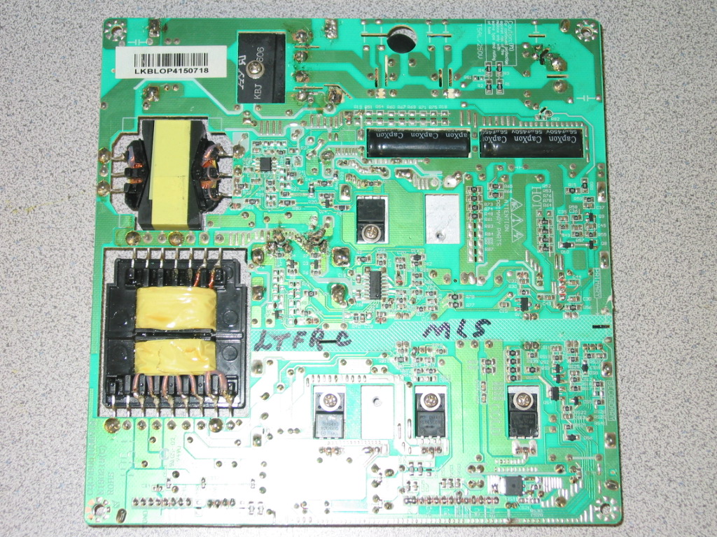
Olevia VLE-42FDVLDRB TV dead, power board BL-OP415601-001 replacement
Synopsis: Recently we've been sent a power board from Olevia VLE-42FDVLDRB LED TV for repair. As many LED power supply modules it wasn't designed with repair options in mind. On top of that someone has messed up badly enough with it to prompt us writing this article.
You can let us repair a board or you can get a replacement power board BL-OP415601-001 for your Olevia VLE-42FDVLDRB, but you can not expect us to fix your attempts of repairing it.
I thought Olevia has gone out of business a few years ago, but apparently they've returned and are now back selling more cheap Chinese TVs. Well who am I to blame it, pretty much everyone does the same these days.
So we received this power board from Olevia VLE-42FDVLDRB, which bottom side raises the promot feeling of a cheap floating and baking so familiar from other RCA branded TVs.
Apparently the board has failed since the main AC fuse was replaced and the reason for the failure must have been either the primary rectifier or, more likely, the pair of driving FETs for the main transformer - Q1 an Q2 located under HS3.
I say "apparently" because someone has already tried workng on those.
Here is how it looked (click to enlarge):
 The main fuse (5A/250V by spec) was replaced with a 7A one.
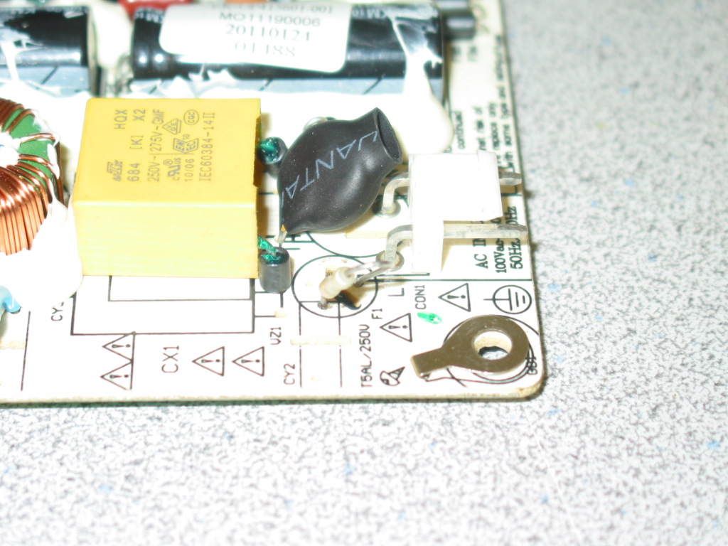 The sole reason one should not do that is because it increases the chances of failing more components on the board should a problem occur, before the fuse blows. It's not the biggest sin in the business, but then again if you combine it with other signs of bad handling you can easily understand why we do not want to repair boards after someone else.
The two transistors were replaced and it was so messy you couldn't be certain if there was a good contact or , possibly, a broken track:
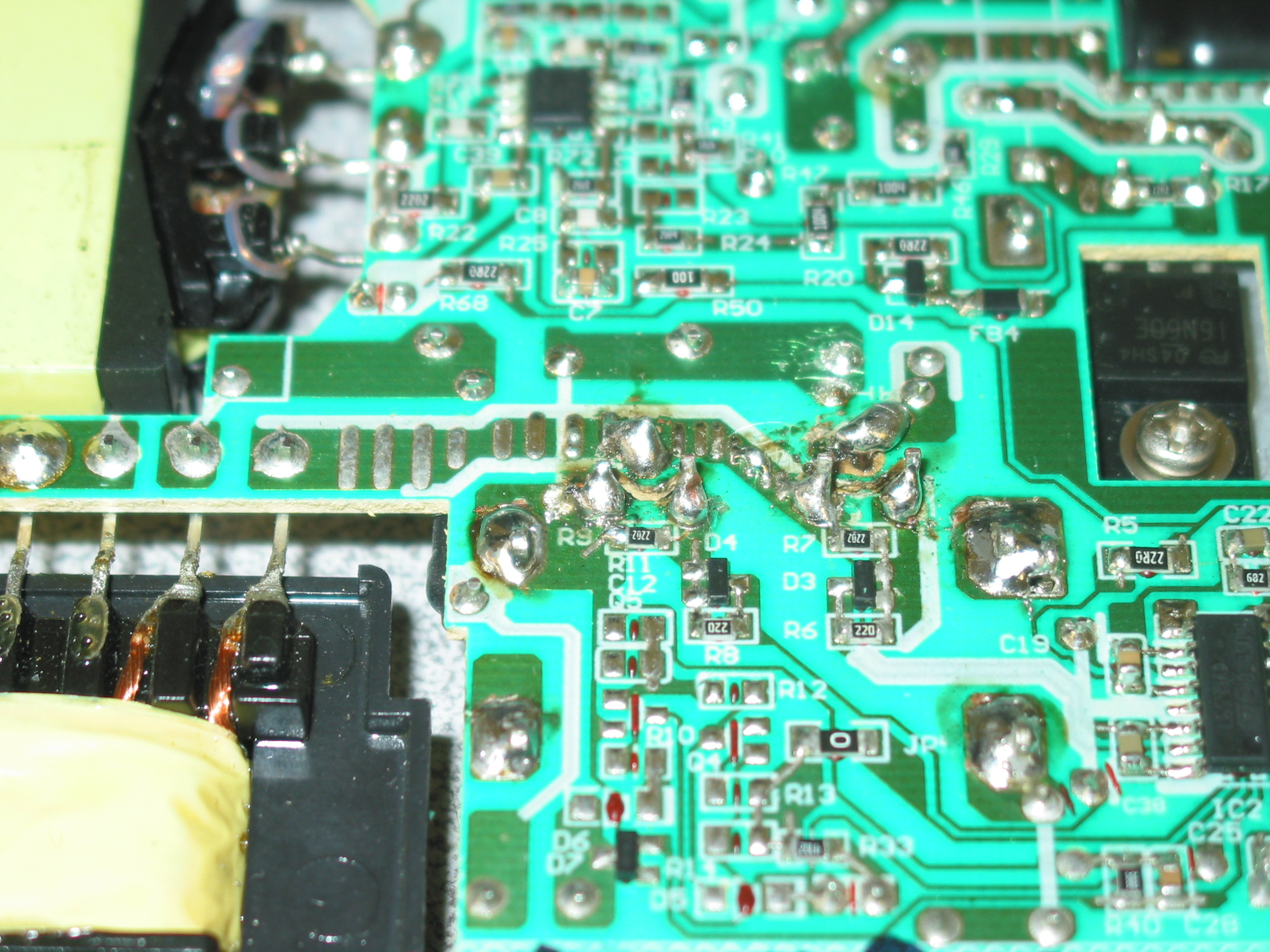 It was the same with the main AC rectifier solder joints:
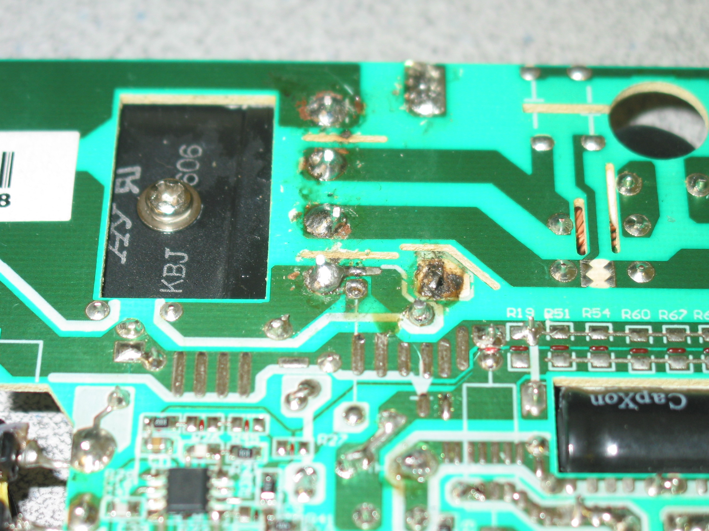 Finally, there was a cold solder join at an opto-coupler for the feedback for the main AC. Can't be seen on the picture unfortunately, but it was clearly man-made, a result of a bad soldering job :
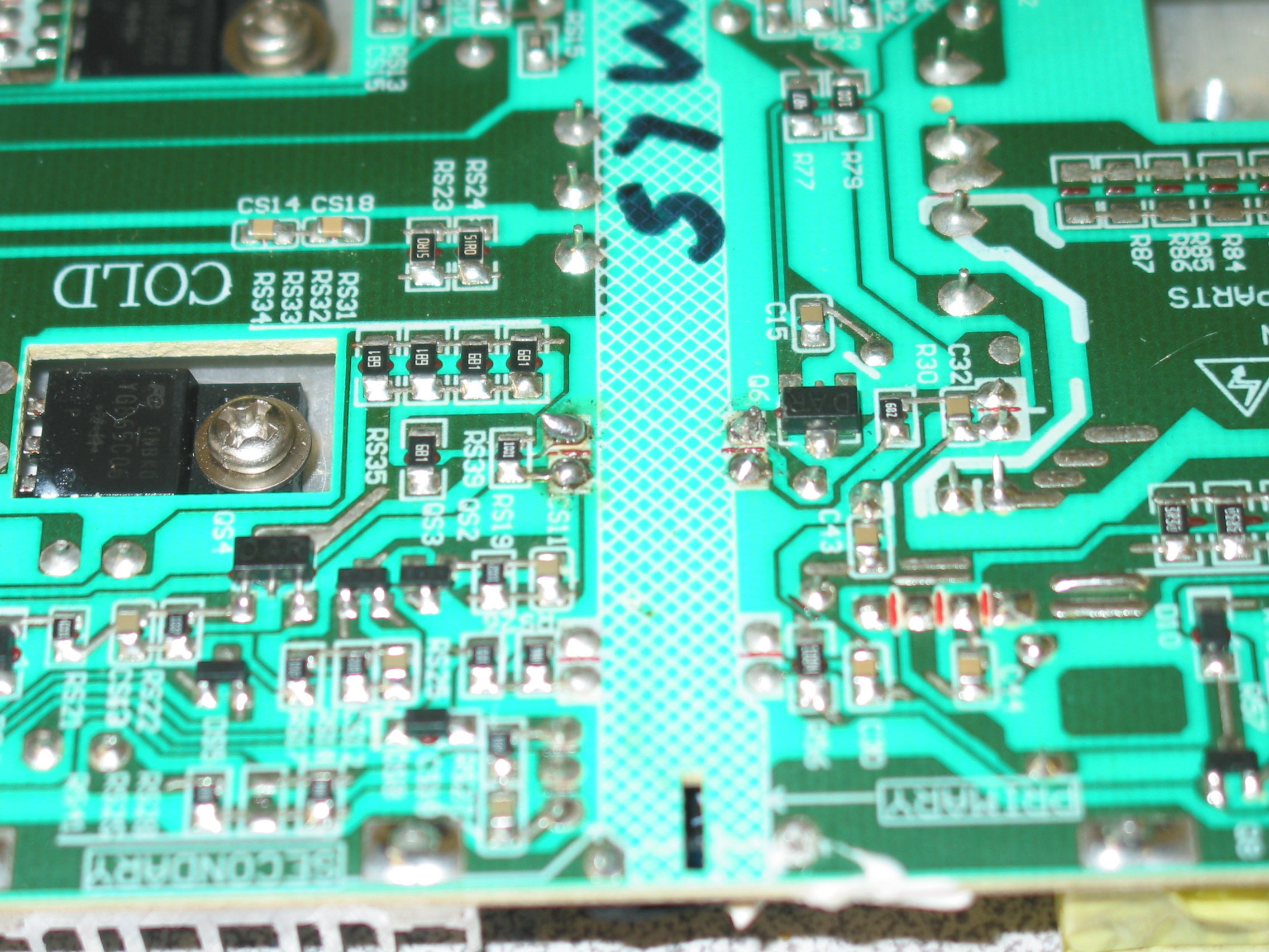
It is extremely easy to miss a cold solder or other uncommon problem on a board.
It is hard enough to fix naturally occurring problems and if you add human-induced ones you easily get what insurance would call "a total loss" - a repair which would end up costing more than a replacement.
So in this particular case we pointed out the customer to a replacement power board BL-OP415601-001 for their Olevia VLE-42FDVLDRB.
We kept the bad core - it won't be of help to them anyway - and if we have enough time we might take a shot at it. But I know from lots of experience it is not going to be fast and easy, let alone profitable.
Speaking of customer-induced problems that are easy to miss I will just add another example that we got yesterday:
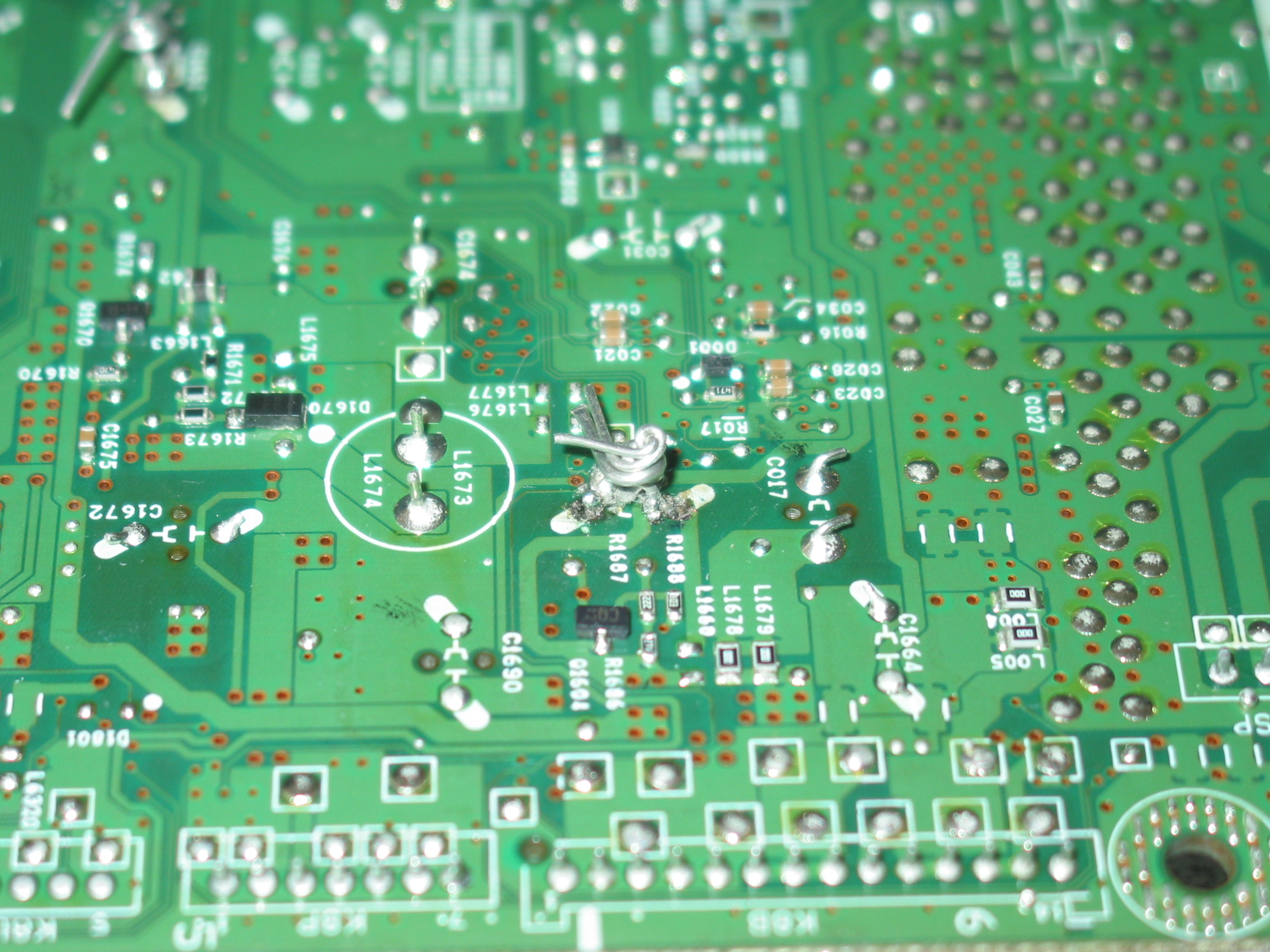
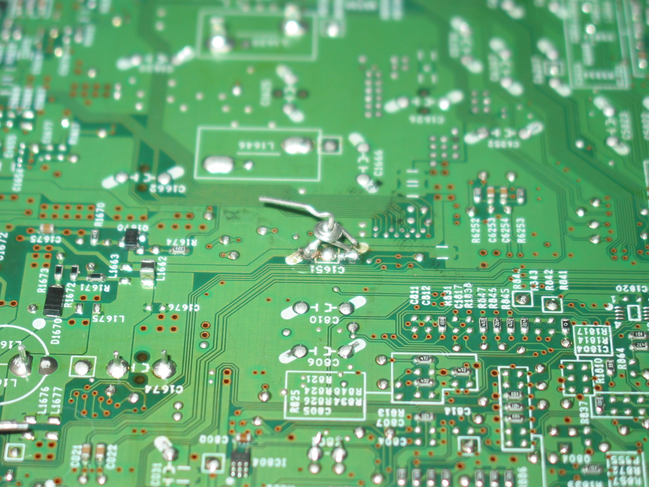
This is from a Sanyo J4FE main board which a customer sent for repair.
Here's the kick: we serviced , tested and returned the board without noticing those (there were two of them) capacitors with shorted and twisted legs.
How could it have worked if it had capacitors' legs shorted and twisted like that? Excellent question!
When removed from the board the original capacitors were not just desoldered. They were more like torn out of the board, removing the copper galvanization in the hole and around it. So when new capacitors were plugged in and wrapped like that for whatever strange reason, they actually were not making contact with the tracks that they were supposed to make contact with, at least not in our tests.
We then received the board back for warranty service and noticed the problem. We told the customer we should not have done a repair in the first place and customer agreed to get all the money back in exchange for leaving us the board.
Eventually we got it working properly (I hope) and we have it listed as an exchange main board for DP50749 P50749-00.
But if we receive a board with similar traces of tampering (and we see them) we'll likely reject servicing it again.
You can let us repair a board or you can get a replacement power board BL-OP415601-001 for your Olevia VLE-42FDVLDRB, but you can not expect us to fix your attempts of repairing it.
I thought Olevia has gone out of business a few years ago, but apparently they've returned and are now back selling more cheap Chinese TVs. Well who am I to blame it, pretty much everyone does the same these days.
So we received this power board from Olevia VLE-42FDVLDRB, which bottom side raises the promot feeling of a cheap floating and baking so familiar from other RCA branded TVs.
Apparently the board has failed since the main AC fuse was replaced and the reason for the failure must have been either the primary rectifier or, more likely, the pair of driving FETs for the main transformer - Q1 an Q2 located under HS3.
I say "apparently" because someone has already tried workng on those.
Here is how it looked (click to enlarge):
The two transistors were replaced and it was so messy you couldn't be certain if there was a good contact or , possibly, a broken track:
It is extremely easy to miss a cold solder or other uncommon problem on a board.
It is hard enough to fix naturally occurring problems and if you add human-induced ones you easily get what insurance would call "a total loss" - a repair which would end up costing more than a replacement.
So in this particular case we pointed out the customer to a replacement power board BL-OP415601-001 for their Olevia VLE-42FDVLDRB.
We kept the bad core - it won't be of help to them anyway - and if we have enough time we might take a shot at it. But I know from lots of experience it is not going to be fast and easy, let alone profitable.
Speaking of customer-induced problems that are easy to miss I will just add another example that we got yesterday:
This is from a Sanyo J4FE main board which a customer sent for repair.
Here's the kick: we serviced , tested and returned the board without noticing those (there were two of them) capacitors with shorted and twisted legs.
How could it have worked if it had capacitors' legs shorted and twisted like that? Excellent question!
When removed from the board the original capacitors were not just desoldered. They were more like torn out of the board, removing the copper galvanization in the hole and around it. So when new capacitors were plugged in and wrapped like that for whatever strange reason, they actually were not making contact with the tracks that they were supposed to make contact with, at least not in our tests.
We then received the board back for warranty service and noticed the problem. We told the customer we should not have done a repair in the first place and customer agreed to get all the money back in exchange for leaving us the board.
Eventually we got it working properly (I hope) and we have it listed as an exchange main board for DP50749 P50749-00.
But if we receive a board with similar traces of tampering (and we see them) we'll likely reject servicing it again.
Subscribe to:
Posts (Atom)