We at Coppell TV Repair do our best to protect ourselves and our customers from bad parts, but ultimately nobody would take care of the customer than the customer himself.
Of course by publishing such information we inevitably also continue to indicate our competitors some of which we are proud to see as subscribed followers of our blog.
For what it's worth, that's the nature of this business.
Competitors, feel free to copy this and post it on your sites...you are going to do it anyway, you might as well do it with our blessing.
Now back to the task at hand.
The tests described below are applicable with the IC on and off board. Of course we strongly recommend that you apply them before you solder any IC on the board - you'll save time and you'll also increase the odds of being able to return the IC back to the vendor with least worries.
Those tests are not complete in a sense that they do not guarantee that the IC will work properly.
But they clearly indicate if it is bad and while it's not guaranteed, we find that 99.9% of the time when an IC passes them it works good on a board.
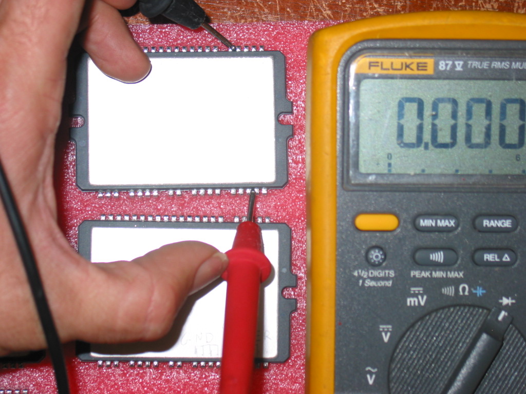
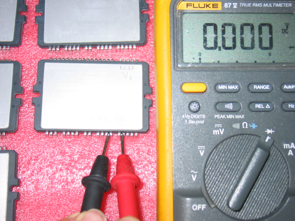
It all boils down to detecting continuity (shorts) or low resistance (ohms) between certain pairs of pins on the module..
If you find one the STK795-518 is certainly bad.
The tests can be done with the IPM on or off the board.
Here's a picture of the pins of interest:
Here's the simple rule:
THERE MUST BE NO CONTINUITY (SHORT) BETWEEN ANY COMBINATION OF THOSE!
IF YOU FIND A SHORT THEN YOUR STK795-518 IS DEFECTIVE.
This is actually 100% correct for all other plasma IPM modules.
There are 4 inputs/outputs which result in 6 possible tests (Vs-GND, Vs-SUSout, Vs-ERout, GND-SUSout, GND-ERout, SUSout-ERout), but in reality two are the most common failures that we see in STK795-518:
1) Vs shorted to one of the two sustain outputs:
2) The other sustain output shorted to ground:


5 comments:
Hi, it looks like the SUS and ER are connected together on the board, is this correct, if so, why is one named SUS and the other ER?
thank you
Horizontal Lines / Bottom Half
All Black / Top Half
Reset Ribbons on Buffers: Response detected when moving adjusting ribbons on lower, though the lines remained.
WITH TV ON - Pushed in on white connectors between buffers and lower buffer / y-sus.
**This was a mistake...
**After pushing in the white connector between the y-sus and the lower buffer, the bottom half became dark just like the top half.
Upper Buffer - Cool to the touch and not responsive. Dead?
Lower Buffer - 1 hot chip, no longer responsive on display, current still passes through from the y-sus (I know this since the chip still overheated in a retest). Just went Dead?
Y-Sus - Visually (didn't remove anything...just a surface look without moving the mounting arm) looks good, no cap bulges, no leaking, no burns. Still good? Dead? Thoughts?
Ok, so, I feel pretty confident that my Lower Buffer is bad. I'm pretty clueless thereafter. I am currently "waiting" for the Lower Buffer.
If the lower is bad, will it stop the upper from working, or is my upper definitely bad too?
More importantly, if the lower JUST blew out, and the TV was turned on twice to test after (both times, black screen, some small random flicker spots at times (looks like static discharges in the display), what are the chances the Y-SUS is still working?
The infamous LED2011 light is blinking GREEN with the LED2010 steady.
There is no red blinking light error.
THANK YOU IN ADVANCE TO ANYONE WHO HELPS ME FIGURE THIS OUT!
Sus er are connected on board so you can't do this test in board....coppell s wrong
@22222222222222: No he is not. He shows how to test an IPM *out* of the board since a lot (possibly all) of the IPMs coming from china are refurbs and quite a few of them come already defective, so that is how they are identified before even making it to the board.
I want to have one(sk 795-518)where to get it
Post a Comment