We are going through the worst server failure we've had in 10 years.
Bear with us and please excuse the temporary problems associated with it - www.coppelltvrepair.com is down and most of the images at blog.coppelltvrepair.com are missing.
Unfortunately email is also down..for the time being you can only reach us through phone at 972 245 1979.
Thursday, April 14, 2011

Tuesday, April 12, 2011
Insignia NS-L42Q-10A / NS-L42X-10A does not power, bad power 715G3196-1
If your Insignia NS-L42Q-10A is completely dead upon connecting to power chances are it has bad power supply.
(come to think of it, the same is true for pretty much any electronic appliance, isn't it? :-)
Well in case of the NS-L42Q-10A and its sister NS-L42X-10A it is rather likely that it's the power board.
I've seen few of those already and they all had similar problem - lack of the standby 5V power and everything else from there on.
The power board's model is 715G3196-1 and it looks like this:

The problem was relatively easy to spot on the first of the boards and a little more obscure on the others.
It was the SMPS driver IC IC901 that was burned. On some boards it has shorted and that did burn a few other components in the circuit.
On some it was apparently burned open and although maybe a bit overheated the other components had survived the failure.
Based on those experiences we've assembled a simple repair kit containing the components that are most likely and usually burned - IC901, ZD906 and R950.
This blog is hopefully useful in confirming that this seems to be a common problem for this board and naming the components you need to pay attention to.
Granted, over time it may turn out there are other problems as well. We'll update the blog if and when we know more.
In the meantime, you can try and source the components by yourself or you can use our kit for what we consider a quite reasonable price.
If you don't then...well, good luck sourcing :-)
And if you don't feel like doing that by yourself...you can always contact us and send the board for repair service at Coppell TV Repair!
(come to think of it, the same is true for pretty much any electronic appliance, isn't it? :-)
Well in case of the NS-L42Q-10A and its sister NS-L42X-10A it is rather likely that it's the power board.
I've seen few of those already and they all had similar problem - lack of the standby 5V power and everything else from there on.
The power board's model is 715G3196-1 and it looks like this:
The problem was relatively easy to spot on the first of the boards and a little more obscure on the others.
It was the SMPS driver IC IC901 that was burned. On some boards it has shorted and that did burn a few other components in the circuit.
On some it was apparently burned open and although maybe a bit overheated the other components had survived the failure.
Based on those experiences we've assembled a simple repair kit containing the components that are most likely and usually burned - IC901, ZD906 and R950.
This blog is hopefully useful in confirming that this seems to be a common problem for this board and naming the components you need to pay attention to.
Granted, over time it may turn out there are other problems as well. We'll update the blog if and when we know more.
In the meantime, you can try and source the components by yourself or you can use our kit for what we consider a quite reasonable price.
And if you don't feel like doing that by yourself...you can always contact us and send the board for repair service at Coppell TV Repair!
Wednesday, April 6, 2011
How to test STK795-518 YSUS IPM for defects
This article will tell you a few quick checks for the most common failures found in Sanyo's STK795-518 used in YSUS board LJ92-01200A and a 50'' plasma sustain board (let me know the number if you have it!).
We at Coppell TV Repair do our best to protect ourselves and our customers from bad parts, but ultimately nobody would take care of the customer than the customer himself.
Of course by publishing such information we inevitably also continue to indicate our competitors some of which we are proud to see as subscribed followers of our blog.
For what it's worth, that's the nature of this business.
Competitors, feel free to copy this and post it on your sites...you are going to do it anyway, you might as well do it with our blessing.
Now back to the task at hand.
The tests described below are applicable with the IC on and off board. Of course we strongly recommend that you apply them before you solder any IC on the board - you'll save time and you'll also increase the odds of being able to return the IC back to the vendor with least worries.
Those tests are not complete in a sense that they do not guarantee that the IC will work properly.
But they clearly indicate if it is bad and while it's not guaranteed, we find that 99.9% of the time when an IC passes them it works good on a board.
It all boils down to detecting continuity (shorts) or low resistance (ohms) between certain pairs of pins on the module..
If you find one the STK795-518 is certainly bad.
The tests can be done with the IPM on or off the board.
Here's a picture of the pins of interest:

As you can see there are 4 points of interest - GND (Ground), Vs (supply power), SUS and ER, which are the two outputs for the sustain and energy recovery accordingly. Those two are shorted on the board, but on an actual IC are NOT connected to each other.
Here's the simple rule:
THERE MUST BE NO CONTINUITY (SHORT) BETWEEN ANY COMBINATION OF THOSE!
IF YOU FIND A SHORT THEN YOUR STK795-518 IS DEFECTIVE.
This is actually 100% correct for all other plasma IPM modules.
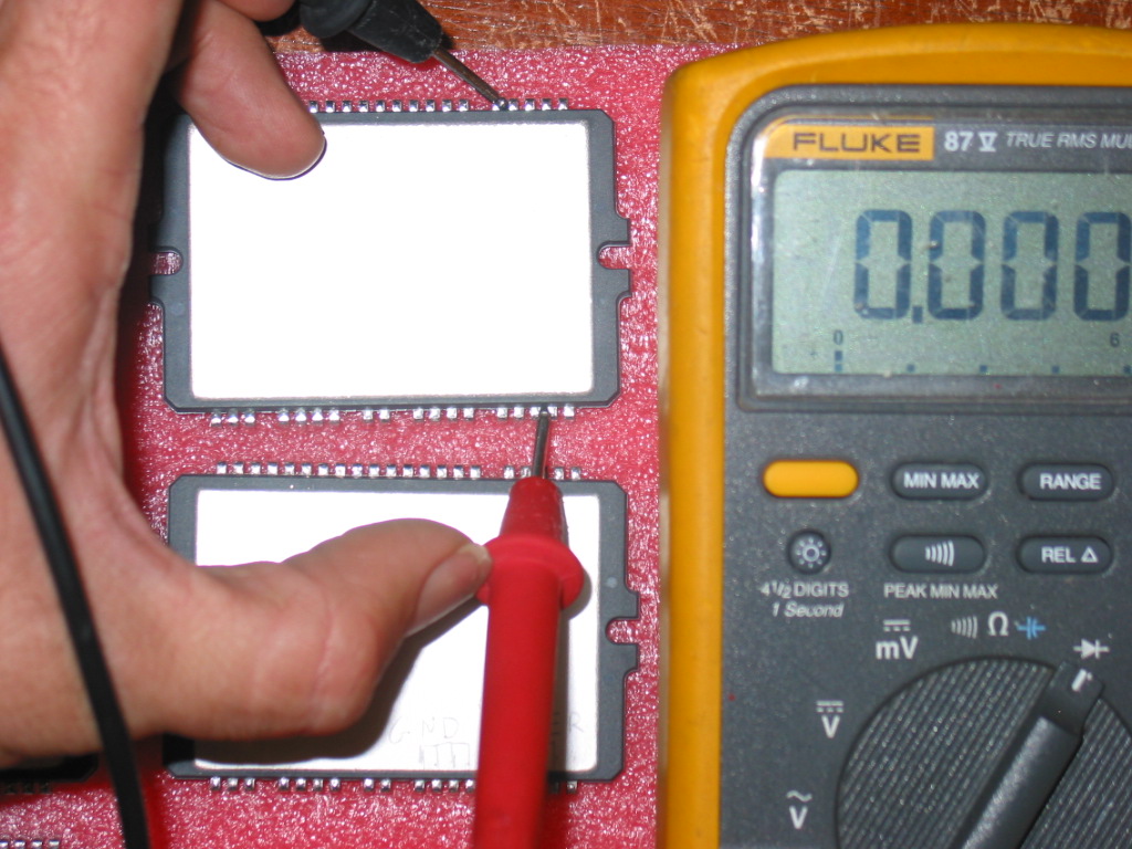
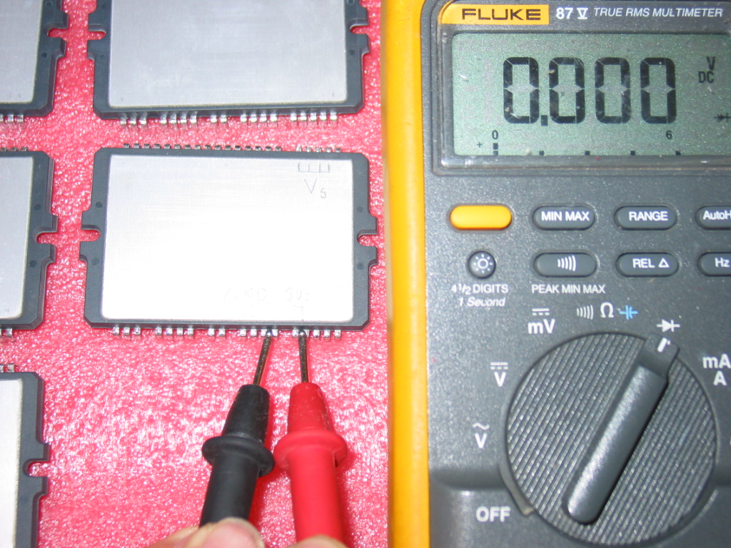
There are 4 inputs/outputs which result in 6 possible tests (Vs-GND, Vs-SUSout, Vs-ERout, GND-SUSout, GND-ERout, SUSout-ERout), but in reality two are the most common failures that we see in STK795-518:
We at Coppell TV Repair do our best to protect ourselves and our customers from bad parts, but ultimately nobody would take care of the customer than the customer himself.
Of course by publishing such information we inevitably also continue to indicate our competitors some of which we are proud to see as subscribed followers of our blog.
For what it's worth, that's the nature of this business.
Competitors, feel free to copy this and post it on your sites...you are going to do it anyway, you might as well do it with our blessing.
Now back to the task at hand.
The tests described below are applicable with the IC on and off board. Of course we strongly recommend that you apply them before you solder any IC on the board - you'll save time and you'll also increase the odds of being able to return the IC back to the vendor with least worries.
Those tests are not complete in a sense that they do not guarantee that the IC will work properly.
But they clearly indicate if it is bad and while it's not guaranteed, we find that 99.9% of the time when an IC passes them it works good on a board.
It all boils down to detecting continuity (shorts) or low resistance (ohms) between certain pairs of pins on the module..
If you find one the STK795-518 is certainly bad.
The tests can be done with the IPM on or off the board.
Here's a picture of the pins of interest:

Here's the simple rule:
THERE MUST BE NO CONTINUITY (SHORT) BETWEEN ANY COMBINATION OF THOSE!
IF YOU FIND A SHORT THEN YOUR STK795-518 IS DEFECTIVE.
This is actually 100% correct for all other plasma IPM modules.
There are 4 inputs/outputs which result in 6 possible tests (Vs-GND, Vs-SUSout, Vs-ERout, GND-SUSout, GND-ERout, SUSout-ERout), but in reality two are the most common failures that we see in STK795-518:
1) Vs shorted to one of the two sustain outputs:
2) The other sustain output shorted to ground:
Saturday, April 2, 2011
From the mailbox - no edits and no refunds!
If that blog was more advanced I'd have that as a thread and allow others to chime in.
I'll just post some of the requests and correspondences we have (if any), without any changes.
Some will be funny, some will be angry, some may even be rude.
Date: 28 May 2011
Subject: Y-sustain LJ92-01200A / LJ41-02759A REPAIR SERVICE
hi I have a tv using this board I bought the lower buffer off an ebayer and it was shorted and blew my y sus board. I basically destroyed the board i got from him . I have an upper buffer that is bad and 2 yus boards one is pulling the power supply down the other runs but when the upper buffer is plugged in the screen flashes every second before that lower buffer i tryed and was shorted i got lines on top half with no lower buffer installed, if i sent you the upper buffer and both logic boards how much would it cost me for a new set of y sus and both upper and lower buffer boards. this tv had a bad lower buffer and i took the ysus for another tv. I bought a replacement that worked unill i got the bad lower buffer I have 2 y sus boards and one upper buffer that is bad but not shorted. thanks Erik
CTVR: ... ?
Date: 28 Mar 2011
Subject: 1032298-HS YSUS BOARD HP PL4260N REPAIR SERVICE
Dear coppelltvrepair,
LGEPDP 051124............. MODEL:42V8&X3................. BOARD:YSUS............ PART NO:6870QYH005B ......... LOC:2XXX........... BOARD SIZE:285X194..... ICAN'T SEE THOSE 'CAUSE THE STICKER? IS FOR A PLASMA TV HP. ONE MORE QUESTION, IT'S WORKING THIS ITEM? THANK YOU
- camiloherevia1983
CTVR: Whatever he or she wants we decided wouldn't be able to provide it.
Date: 11 May 2011
Dear coppelltvrepair,
is i am buy this item or do send you this item
- jassnyder197979
I'll just post some of the requests and correspondences we have (if any), without any changes.
Some will be funny, some will be angry, some may even be rude.
Date: 28 May 2011
Subject: Y-sustain LJ92-01200A / LJ41-02759A REPAIR SERVICE
hi I have a tv using this board I bought the lower buffer off an ebayer and it was shorted and blew my y sus board. I basically destroyed the board i got from him . I have an upper buffer that is bad and 2 yus boards one is pulling the power supply down the other runs but when the upper buffer is plugged in the screen flashes every second before that lower buffer i tryed and was shorted i got lines on top half with no lower buffer installed, if i sent you the upper buffer and both logic boards how much would it cost me for a new set of y sus and both upper and lower buffer boards. this tv had a bad lower buffer and i took the ysus for another tv. I bought a replacement that worked unill i got the bad lower buffer I have 2 y sus boards and one upper buffer that is bad but not shorted. thanks Erik
CTVR: ... ?
Date: 28 Mar 2011
Subject: 1032298-HS YSUS BOARD HP PL4260N REPAIR SERVICE
Dear coppelltvrepair,
LGEPDP 051124............. MODEL:42V8&X3................. BOARD:YSUS............ PART NO:6870QYH005B ......... LOC:2XXX........... BOARD SIZE:285X194..... ICAN'T SEE THOSE 'CAUSE THE STICKER? IS FOR A PLASMA TV HP. ONE MORE QUESTION, IT'S WORKING THIS ITEM? THANK YOU
- camiloherevia1983
CTVR: Whatever he or she wants we decided wouldn't be able to provide it.
Date: 11 May 2011
Dear coppelltvrepair,
is i am buy this item or do send you this item
- jassnyder197979
Thursday, March 24, 2011
How to uninstall 6871QYH053B and compatible boards from 42'' plasma TV
People often ask me how to uninstall the YSUS board 6871QYH053B (or some of its compatible models - 6871QYH048B for example) from their 42'' plasma TV.
Coppell TV Repair services those boards and the question is natural considered we expect you to send us the board for repair.
This is a really quick tutorial that is board-independent and TV model independent.
It is important to say that while different board models do not have any differences in regards to dismantling procedure, the TV models may make it a bit different as to how do you get to the board.
Again, this short guide is aiming at all models and I will point out where differences are expected.
To uninstall the board, first lay the TV flat on the floor, face down.
Unscrew and remove the base, as most of the time it gets in the way. Sometimes it does not, but we usually remove it when we work on a TV.
After taking all the bolts of the cover (and sometimes ones that we shouldn't take out) and removing the cover we look at something like this:
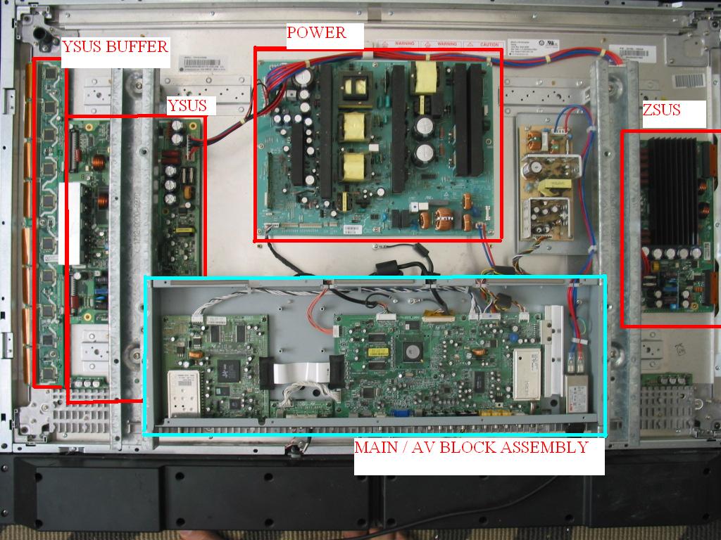
On all plasma TVs that I have seen the YSUS is on the left and the ZSUS is on the right. They look differently in different makes and models, but they are always left and right and YSUS is always a bit bigger than ZSUS.
Otherwise they share a lot of functionality and, logically, appearance.
Anyway, the trick to pulling out the YSUS is usually getting access to the lower right corner of the board where there's a screw in the corner and - in this case - a very fragile flat ribbon cable connector.
To get to there, you often need to uninstall and move the whole central block assembly containing the main board:
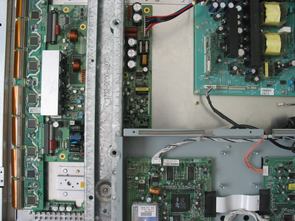
In this case, there were two bolts on each side that were holding the assembly, plus three more on the bottom that were holding an L shaped metal supporting the assembly by tying it to the chassis.
In your case this may be slightly different and in some cases you may also need to remove the vertically standing support bar used for both wall mounting and construction support. At least we've done it a few times but most of the times - possibly always - you can get away without having to do that.
After all the bolts affixing the main board assembly are removed, you can simply pull it up and/or push it to the side:
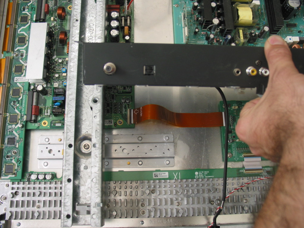
As I said what you're aiming at is access to the lower right screw of the YSUS board and, of course, the fragile connector P8 just above it.
This is how the beast looks up-close:
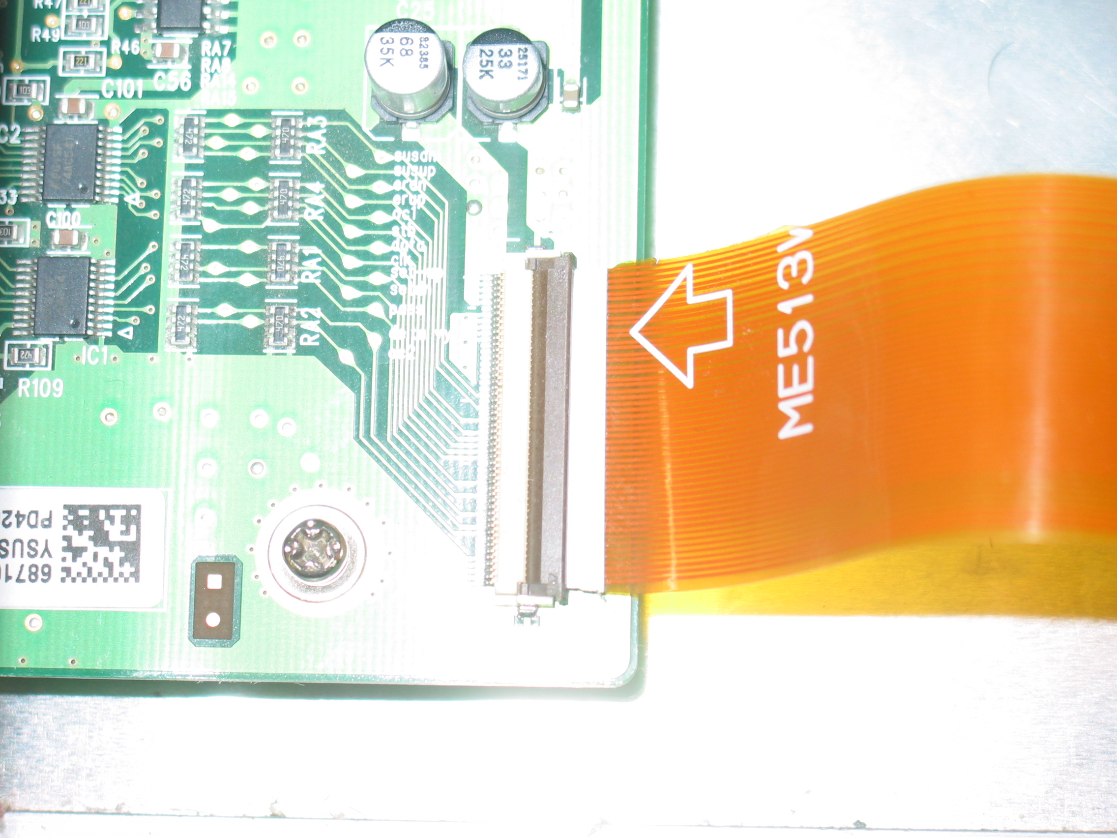 Again, it is OK that your cable is white and ours is not. We're the pros, we can afford better cables, wink-wink.
The cable in your TV will likely be white and not orange-brownish as in our picture. Do not pay attention to the color and please do not call to ask if that is a sign of anything. It isn't.
To uninstall the cable, you need to flip the right side of the brown plastic covering the flex cable so that from horizontal it turns vertical. The hinges are at the ends on the left side and are extremely fragile.
I hear there are special tools that let you open it, but I am old school with fingernails and do it this way:
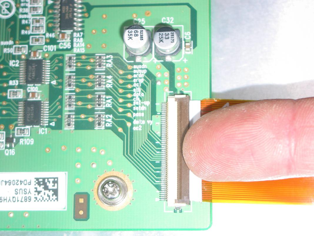
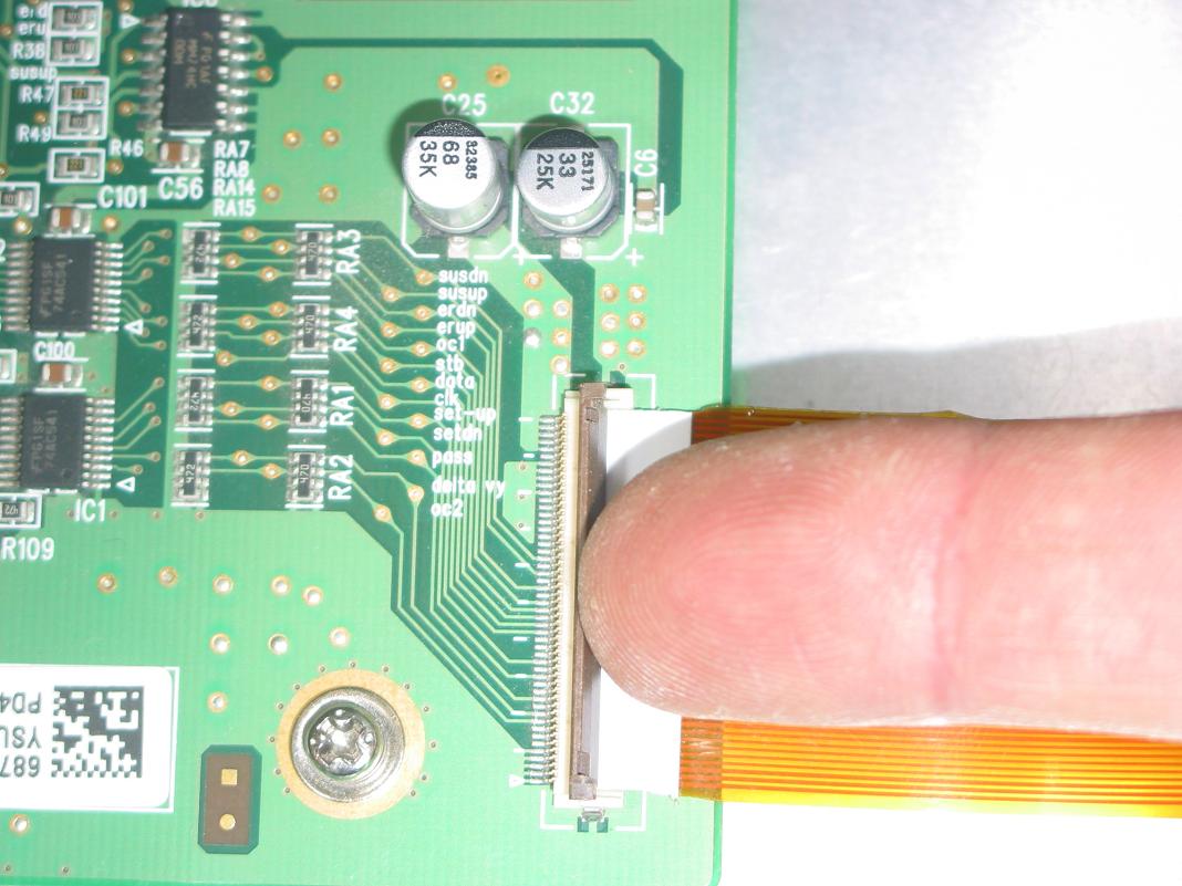
If you can't make a difference between the two pictures, look at how the brown cover is already flipped up on the second one.
The trick for me is to have relatively wide access of the force that pulls up and to also push a little bit inwards in addition to upwards.
Wide contact is necessary so that you actually make the whole length of the cover to wish to turn up. If you apply force only in one point in the middle the brown cover will likely bend and break the hinges.
So if you are using a screwdriver make sure you get one with wider tip.
A great idea is to use two fingers if you can do it - pointing and middle finger work great.
Coppell TV Repair services those boards and the question is natural considered we expect you to send us the board for repair.
This is a really quick tutorial that is board-independent and TV model independent.
It is important to say that while different board models do not have any differences in regards to dismantling procedure, the TV models may make it a bit different as to how do you get to the board.
Again, this short guide is aiming at all models and I will point out where differences are expected.
To uninstall the board, first lay the TV flat on the floor, face down.
Unscrew and remove the base, as most of the time it gets in the way. Sometimes it does not, but we usually remove it when we work on a TV.
After taking all the bolts of the cover (and sometimes ones that we shouldn't take out) and removing the cover we look at something like this:
On all plasma TVs that I have seen the YSUS is on the left and the ZSUS is on the right. They look differently in different makes and models, but they are always left and right and YSUS is always a bit bigger than ZSUS.
Otherwise they share a lot of functionality and, logically, appearance.
Anyway, the trick to pulling out the YSUS is usually getting access to the lower right corner of the board where there's a screw in the corner and - in this case - a very fragile flat ribbon cable connector.
To get to there, you often need to uninstall and move the whole central block assembly containing the main board:
In this case, there were two bolts on each side that were holding the assembly, plus three more on the bottom that were holding an L shaped metal supporting the assembly by tying it to the chassis.
In your case this may be slightly different and in some cases you may also need to remove the vertically standing support bar used for both wall mounting and construction support. At least we've done it a few times but most of the times - possibly always - you can get away without having to do that.
After all the bolts affixing the main board assembly are removed, you can simply pull it up and/or push it to the side:
As I said what you're aiming at is access to the lower right screw of the YSUS board and, of course, the fragile connector P8 just above it.
This is how the beast looks up-close:
The cable in your TV will likely be white and not orange-brownish as in our picture. Do not pay attention to the color and please do not call to ask if that is a sign of anything. It isn't.
To uninstall the cable, you need to flip the right side of the brown plastic covering the flex cable so that from horizontal it turns vertical. The hinges are at the ends on the left side and are extremely fragile.
I hear there are special tools that let you open it, but I am old school with fingernails and do it this way:
If you can't make a difference between the two pictures, look at how the brown cover is already flipped up on the second one.
The trick for me is to have relatively wide access of the force that pulls up and to also push a little bit inwards in addition to upwards.
Wide contact is necessary so that you actually make the whole length of the cover to wish to turn up. If you apply force only in one point in the middle the brown cover will likely bend and break the hinges.
So if you are using a screwdriver make sure you get one with wider tip.
A great idea is to use two fingers if you can do it - pointing and middle finger work great.
Saturday, February 26, 2011
MLT168A power for ILO LCT27HA36 , AKAI LCT2785TA - how to test and more
MGMEET MLT168A is very similar to MLT166A about which I had blogged before.
Here is how it looks from the top:
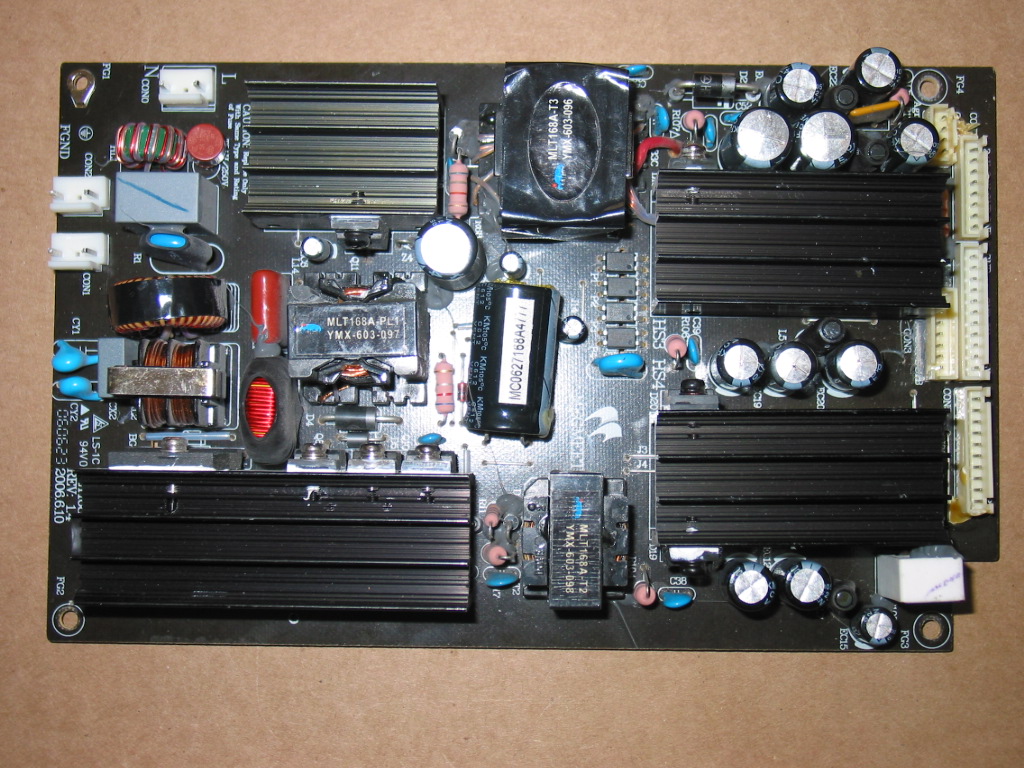
The power input is the single one at the upper left corner, just below the top edge of the board. Its pins are marked with N and L.
All the outputs are on the right side of the board.
When AC is connected to the board there is a single 5V output and it is on the connector marked CON3.
Those 5V are called standby voltage and are used to tell the power board, through another pin on CON3 to wake up and generate all other voltages needed for the normal TV operation.
Using a voltmeter you can check if you have 5V on the appropriate pins on CON3 as per the following illustration (click to see full image):

So, once again, when power board is supplied AC the only output voltage that should be there is the +5V standby voltage. Using a voltmeter you should be able to measure 5V between either of the two pins as displayed above and the ground (which is any of the Ground pins or the TV chassis).
To turn on the rest of the voltages you need to pass the +5V from the standby to the POWER_ON pin.
If there's a cable plugged in in CON3 you can use a wire to short those two. It's OK to short +5V directly there for reasons we will see in a minute.
We didn't have a good connector so we turned the board and soldered a short wire between those two.
Here is how the back of the board looks where the output connectors are:
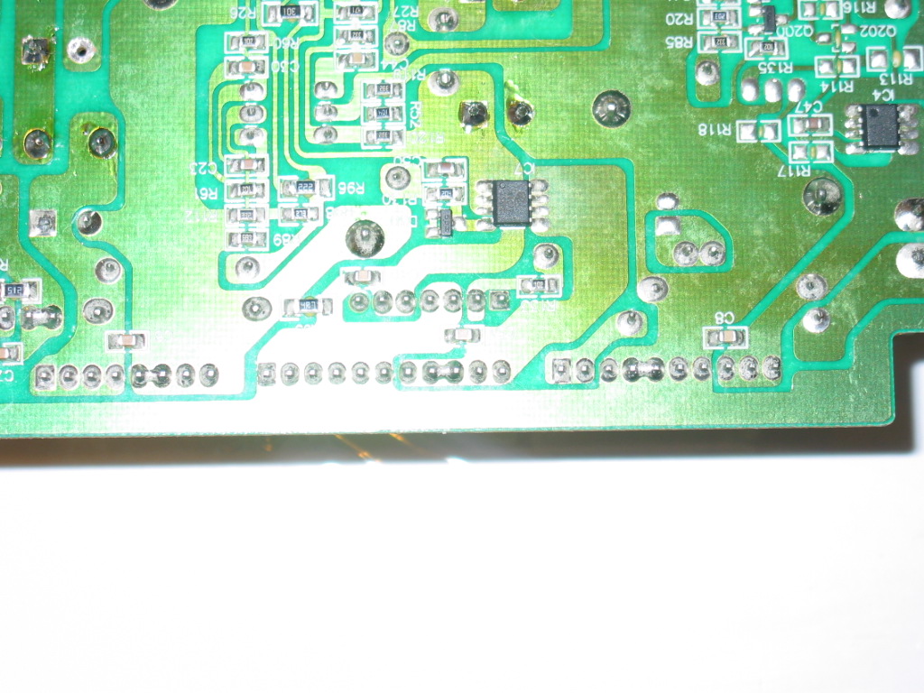 And here is what it looks like when we passed the +5V to the POWER_ON pin:
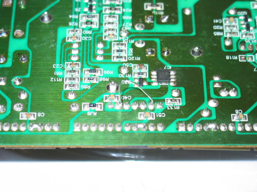 While usually it is not recommended to pass +5V directly to anything (just out of precaution) in this case it is easy to see that there is a resistor (R133) at the input of the POWER_ON line. This means it is completely safe to pass +5V directly there.
Once you have signaled (turned on) the power board you should be able to measure all other voltages as indicated at the top side of the board near the connectors - +12V, +9V and +24V.
Note they may be slightly off the printed values. If you get 11V instead of 12V that's OK as long as it is stable.
If it fluctuates or if it is off by more than 10% you've got a problem.
And if you've got a problem you know who to call.
No, AFTER the ghost busters!
Here is how it looks from the top:
The power input is the single one at the upper left corner, just below the top edge of the board. Its pins are marked with N and L.
All the outputs are on the right side of the board.
When AC is connected to the board there is a single 5V output and it is on the connector marked CON3.
Those 5V are called standby voltage and are used to tell the power board, through another pin on CON3 to wake up and generate all other voltages needed for the normal TV operation.
Using a voltmeter you can check if you have 5V on the appropriate pins on CON3 as per the following illustration (click to see full image):
So, once again, when power board is supplied AC the only output voltage that should be there is the +5V standby voltage. Using a voltmeter you should be able to measure 5V between either of the two pins as displayed above and the ground (which is any of the Ground pins or the TV chassis).
To turn on the rest of the voltages you need to pass the +5V from the standby to the POWER_ON pin.
If there's a cable plugged in in CON3 you can use a wire to short those two. It's OK to short +5V directly there for reasons we will see in a minute.
We didn't have a good connector so we turned the board and soldered a short wire between those two.
Here is how the back of the board looks where the output connectors are:
Once you have signaled (turned on) the power board you should be able to measure all other voltages as indicated at the top side of the board near the connectors - +12V, +9V and +24V.
Note they may be slightly off the printed values. If you get 11V instead of 12V that's OK as long as it is stable.
If it fluctuates or if it is off by more than 10% you've got a problem.
And if you've got a problem you know who to call.
No, AFTER the ghost busters!
Friday, February 18, 2011
Repair, trade-in or buy - comparisons and explanations
Dear coppelltvrepair,
Do you guys have any of these (6871QYH039A 6871QYH039B or 6871QYH039C ) in stock to ship out now or would you have to wait to get mine and then repair it and then ship it back to me?? I need this fixed as soon as possible, I have a customer waiting on it. Thanks a lot :)
Do you guys have any of these (6871QYH039A 6871QYH039B or 6871QYH039C ) in stock to ship out now or would you have to wait to get mine and then repair it and then ship it back to me?? I need this fixed as soon as possible, I have a customer waiting on it. Thanks a lot :)
- fsm_derek
We often receive questions like that from customers and service technicians alike.
Naturally, everyone likes to get their TV working ASAP.(*).
In fact, I have blogged about that earlier, giving an answer to customers requesting that a board is sent to them before their board reaches us.
Now I'd like to take that a step further and explain how we see things.
When getting a new board a customer has four major options: purchase, repair service, exchange service and trade-in service.
PURCHASE is the typical and most common American operation, along with trashing. I.e. you purchase what you need, wait until you receive it and then dutifully bring to the trash whatever was in its place before that. (**).
The EXCHANGE SERVICE , as the name suggests, suggests that you send something in and get a working version of the same thing in its place. Usually the logic is that the replacement is sent as soon as the exchange is received and most customers really want to do it even only with a proof of shipping or "are used to doing it that way with George Electronics" (***).
Coppell TV Repair used to do exchanges until we realized that 80% of the boards that we were receiving had been worked on, broken, used for parts, shoved in the ground, chewed by dogs and you-dont-want-to-know-what-else.
But you get the point. The majority of the boards we were getting were only good for parts.
There's also another reason why exchange is risky and it is worth for it to be explained, because decent folks who send good boards must also understand why are we rejecting them: boards often have unique components on them.
For example every power board and every plasma sustain board have transformers on them which are uniquely made for that board.
If the transformer burns there is usually no place to get it from. It is made especially and only for that board and since the manufacturer does not want anyone but them to service those boards (****) then the only place to get that component would be another board - working or broken.
As every service center we always have a few broken boards neatly stacked under somewhere around, but problems tends to arise in the same areas of a module and soon we find that all such faulty boards miss the same transformer.
In other words, sometimes we can't restore a board even if it has not been tampered with.
The failure rate is different for the different modules, of course, but the core of the problem is the same: exchange may practically end up meaning sale since what we get back may turn out to be just useless.
Without a source of unique components / broken boards exchange is a risky business for the provider, which is probably why it is not at all popular in this business.
REPAIR SERVICE means that the customer sends in a module, the vendor receives it, repairs it and sends it back to the customer. It's usually the cheapest of all options (*****) and that is its major benefit.
The drawbacks are that it is slow and also insecure.
It is slow because it takes time from initiation to completion. Module needs to be sent back and forth and that alone kills a good week at best. Then you have service time on top of that.
And this is where insecurity comes - the vendor may be overloaded with work, their testing environment (6) may shatter to pieces (speaking from experience here) or the problem on the board may be tricky and take longer to resolve than usual.
Worst of all, it may turn out to be practically unsolvable - see the explanation for the unique components in the exchange service section.
Without complete sourcing solution for replacement parts repair is never guaranteed.
At the time of writing this article none of the repair services that we offer is completely guaranteed!
There is more to be said about repair services in general, but the take-away from here is that it is cheap because it is not secure. Vendor can always call customer, apologize and cancel (7).
The TRADE-IN SERVICE is well known and widely used. The first that comes to mind is car dealerships: you get raped on the way in and on the way out.
That's how I used to think until I got in the repair business..
Customer orders a board and expects to receive it before the vendor receives their board back.
Customer is OK with the concept of having to pay a bit more upfront, but expect to get that recovered upon their board's arrival.
But for reasons explained above (can't argue with statistics!) it is not only easier, but I'd say a must for the vendor to assume that what they'll get in is a junk. Even if it does look OK, you can only know if it's OK when you do a full service on it - and by then it may be too late as you'd have already spent time and money on trying to restore it.
The bold conclusion is that TRADE-IN and EXCHANGE services CAN NOT cost as much as a REPAIR!
TRADE-IN and EXCHANGE offer less waiting time (no shipping back and forth) and less risks to the customer (board that's coming has been serviced and tested).
In a free market that ultimately translates to a higher price!
How much higher? Well the extreme is the price of the core - the bare defective board. Usually it is less.
This has become another lengthy article with many undefined assumptions and still doesn't say even half of what I want to say on the subject.
But I'll stop here and imagine I am trying hard to learn to express myself more simple and clear in future.
Gosh I love leaving comments under line! (8)
Thank you for reading all the way up to here...your thoughts are appreciated!
- Bobby
________________________________
* Otherwise bad things may happen. Like looking out of the window, reading a book or, God forbid, dropping by unexpected by a friend just to say hi.
** Does not apply to spouses, gym subscriptions and HOA dues. Otherwise would would have been perfect.
*** To which we automatically reply "then why don't you keep on doing it?!". Poor George Electronics!
**** Service?! "We recommend you replace all three modules", says the manufacturer. "And that's a total of $350". Which is only 80% of the cost of a brand new TV with a year warranty. It's good to be a manufacturer in a world of AOL users!
***** Unless, of course, provided by a authorized/certified/glorified dealer.
6) Sounds more complicated than "TV".
7) "Sorry, dude...it's a bad mess...been working on it for 10 hours and it wouldn't bulge. I give up and you owe me too much, but if you give me $100 I won't press charges for more..."
8) I warned you!
Subscribe to:
Posts (Atom)