Showing posts with label hints. Show all posts

Sunday, October 2, 2011

When 6871QYH039B fails, should buffers be replaced too? (same for 6871QYH039A, 6871QYH039B)

Question:

Hi. My concern is should I go ahead and get the Y-buffers too. Cant a bad buffer blow the new Y-sus? How can I check the buffers without replacing the Y-sus? Do you carry the buffers? Thanks, Geo.


Answer:
With this particular YSUS, an in fact with most sustain boards made by LG (at least in the 2004-2007 models) I would not worry about the buffers when a YSUS fails for several reasons:
 
First, the popular concept that when YSUS fails one should look for the buffers is most likely coming from the Samsung designs from the same time period. LG electrical design is similar and does not have the same failure characteristics as the Samsung boards.
In the Samsung cases it's the buffer board that fails first and damages the YSUS.

With LG, the sustain actually fails before the buffer and usually does not affect it.
Second, when the LG buffer ultimately fails (because that can happen too) it does not tend to damage the sustain. It is possible for it to happen, but it is rare.
 
Instead, when an LG plasma buffer board fails (e.g. in Toshiba 42HP66 or  50HP66) it will typically cause a vertical line as explained in this previous article.

As with any failure it is not guaranteed that it will happen that way. It's just the most common result.
 
So, in a nutshell, it's not worth worrying about the buffers at the time when you know the problem is in the sustain.
It's not bad to check them, but it would be unusual for them to have failed at the same time with the YSUS.


Saturday, October 1, 2011

LG 42PC5D YSUS EBR36954501 EBR39214401 question

Question: 
I am trying to fix an LG 42PC5D, no picture, does not pre-warm up the screen, the fuse on the YSUS board FS5 1.5 amp is blown, it blew again after replacing, it is connected to the STEP-UP/FLYBACK SWITCHING REGULATOR on the board, I don't have a schematic and working on plasma is new, without tracing the circuit board traces, is this something this driver chip would fix this problem?


Answer:

It might or might not, I can't promise.

That fuse doesn't usually burn when the IPM fails. It is not impossible for it to happen, of course, but if I were you I'd search where the high current to blow the fuse is coming from.

It may or may not be the IPM.

Friday, September 30, 2011

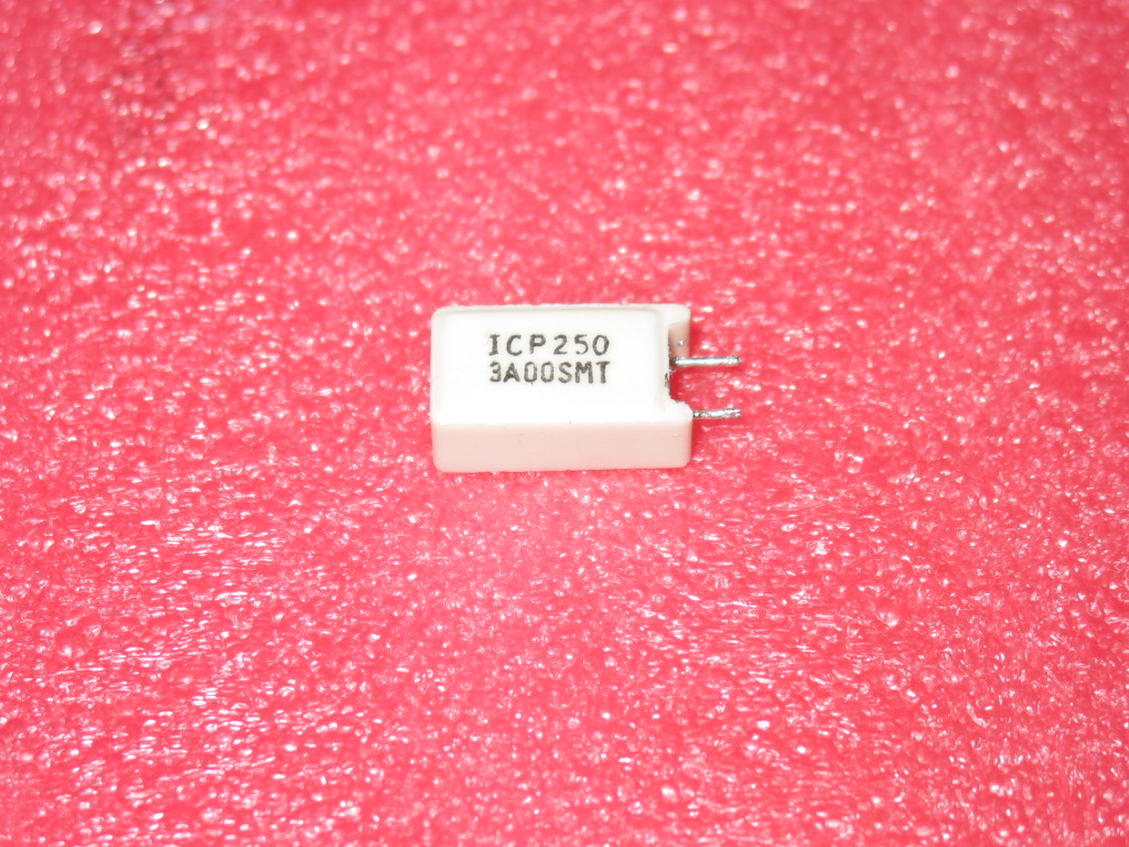
ICP250 3A00SMT datasheet or equivalent substitute? Lucky you!

If Google has ranked this page high enough for you to land here while looking for a substitute or at least the damn value of that damn resistor with marking  ICP250 3A00SMT then you're in luck.


The damn value is 0.16 Ohm at 5 watt.

A good American (i.e. documented and distributed in America) substitute is TWW5JR15E. It is not exactly equivalent, but it is definitely a good substitute. 

I know because I use it for some time.

Now, this is not going to make me serious money, but as a sign of your gratitude you can (if you wish!) order two of the above from the below button. 

(It is two because in my world buying one of anything worth less than the postage to receive it is impractical; for that matter, if you want more just drop me an email.)


ICP250 3A00SMT REPLACEMENT / SUBSTITUTE (2 PCS):


A word of caution: This is reasonably powerful as far as resistors go. It is used in power boards like YPSU-J017A, TV sustain boards and possibly other power modules in consumer electronic devices.

This resistor does not burn without a reason!

You're probably going to have to replace more parts on that board!

Wednesday, September 21, 2011

How to test DELTA DPS-336AP from LVM-37W1 Westinghouse

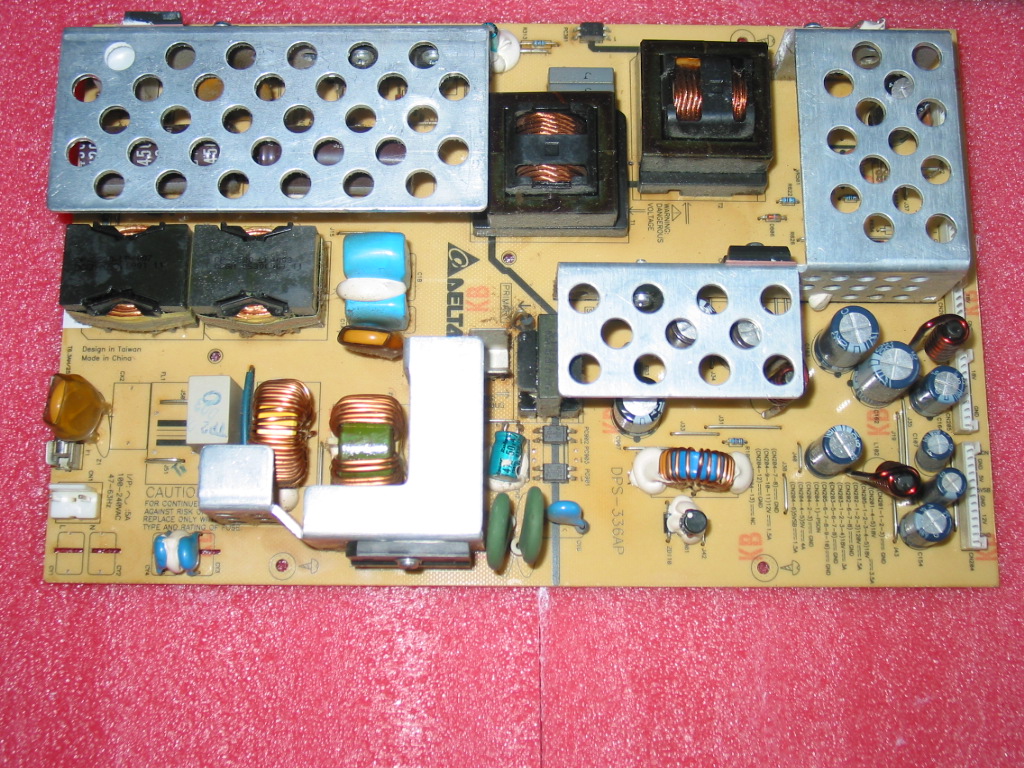
Power board DELTA DPS-336AP is used in Westinghouse LVM-37W1 and possibly other LCD TVs.

It looks like this:

The board is hard to find and expensive , even second hand.

Coppell TV Repair offers a repair service for it and it is somewhat affordable compared to the price of a used board (let alone availability), but before you send it in you will want to check for yourself if it really needs the repair at all.

It's actually easier than many people think. You will need a voltmeter and if you don't have one I seriously suggest going to Walmart and buying one. Seriously, it's worth.

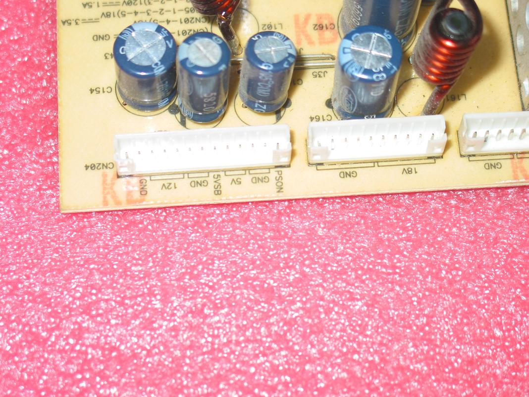
Here's the board's main connector (click to see larger):

When connected to power, the board produces a single 5V standby voltage which goes to the pin marked "5V STB", which is the 6th pin counting backwards.
You can measure 5V between "5VSTB" and any "GND" pin on any connector.

To activate the rest of the voltages on the board (wake up the board) you will need to ground the very last pin on the connector called PSON.

This often misleads people as most power boards require active 5V in order to activate the board and when they pass the 5VSTB to PSON and nothing happens they decide the board is bad.

Well in case of this and some other boards you need to ground the active signal to tell the board to wake up.

Here this is very nicely done as you can simply use the voltmeter's negative probe to short the two pins - PSON and GND which is on its left side; this allows, at the same time, to activate the power supply and get ground for the voltmeter so you can test the other voltages as indicated on the board next to the connectors.

Good luck!

Thursday, September 8, 2011

4H.V1838.401 inverter hacking for Insignia NS-LCD37 LCD TV

This is a quick post for all the poor suckers who are trying to find 4H.V1838.401/D for a reasonable price.

I know how it feels, I was one of them myself when I bought a malfunctioning Insignia NS-LCD37 for $25 and diagnosed it with band inverter.

Well, at the time of writing this there weren't any good replacements to be found, not for a decent price anyway.

You could buy the transformers on eBay for $25 per piece, but I would have needed at least two PLUS at least two FETs that I found shorted and God only knows what else. That's easily $60, not to mention the FETs weren't available anywhere either and I would have to find and use substitutes...

This was easily a bad proposition so I set out to searching a replacement rather than repairing the inverter. You don't expect to pay more than $60 for a 37'' LCD inverter anyway...at least I don't and you shouldn't either.

In fact, I paid even less since I happened to have one handy.

Only it wasn't 4H.V1838.401/D.

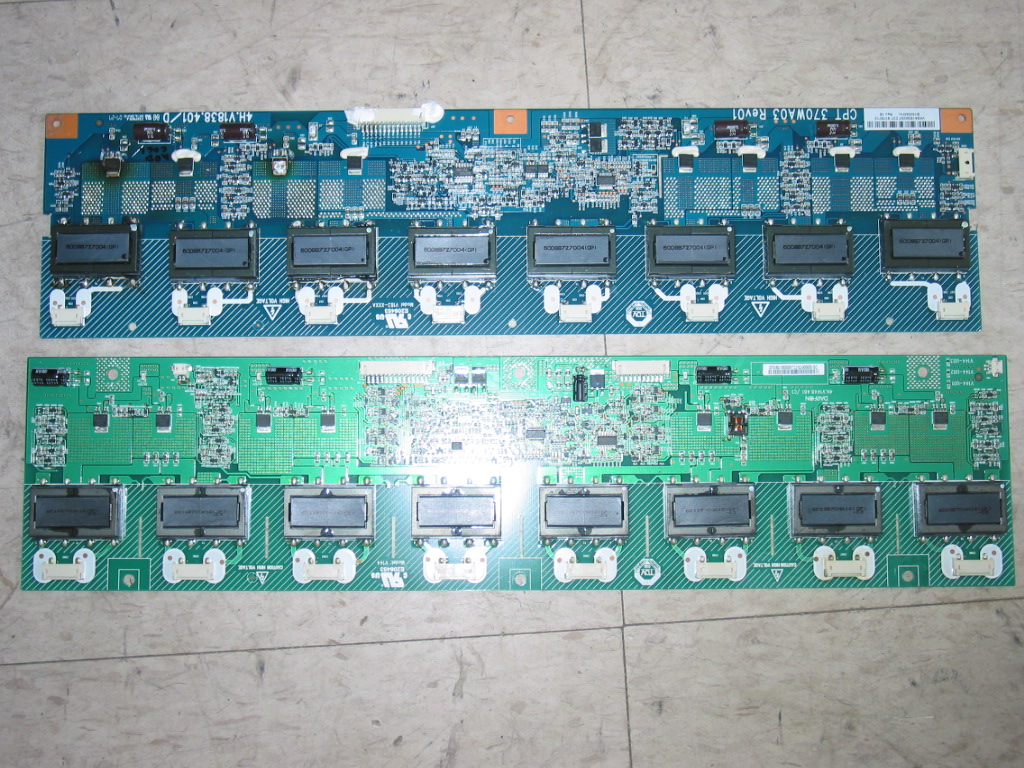
It was 4H.V1448.481/C1 used in the next Insignia model, NS-LCD37-09.

Which is a totally different beast altogether, but that's another story.

The point is, while not an exact match, it is widely available, cheap and does the job!
What more could you want?!

Ah, pictures...right:


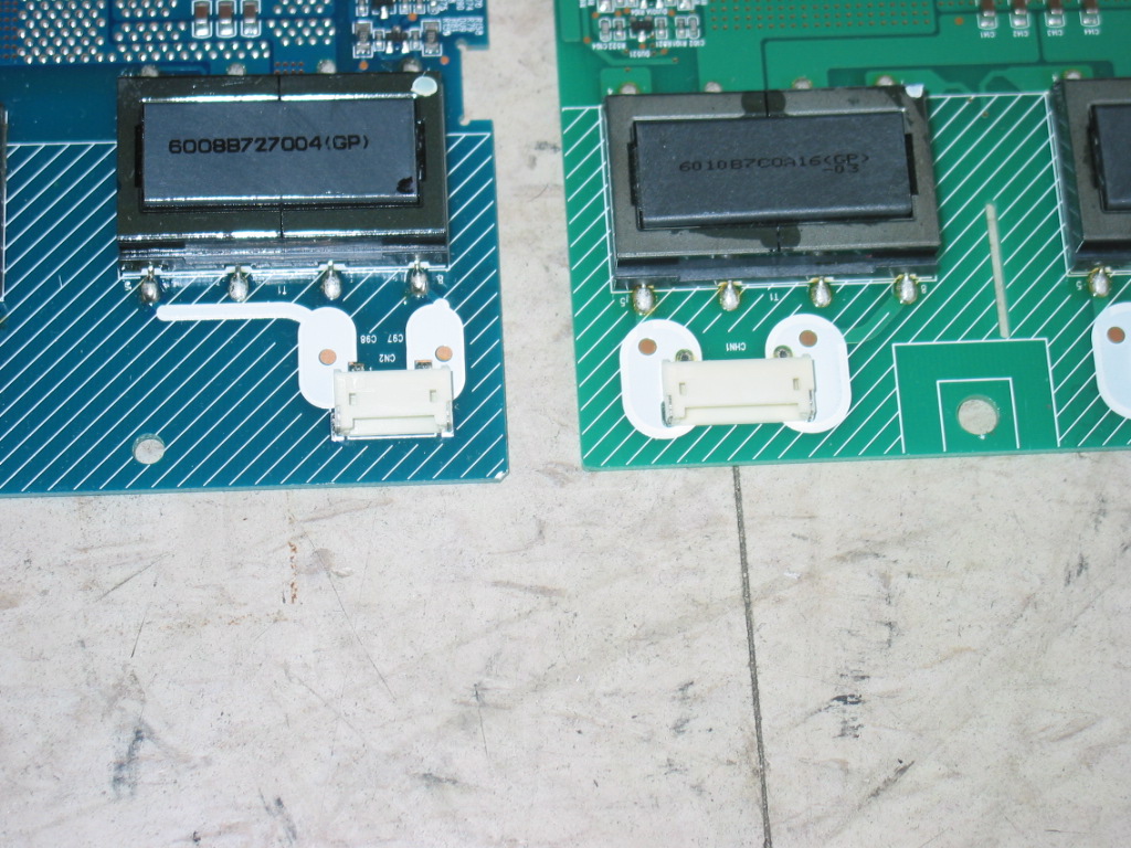
Here are the two inverters next to each other:

The first problem, as you will see, is that the connectors for the CCFL wires are different sizes:

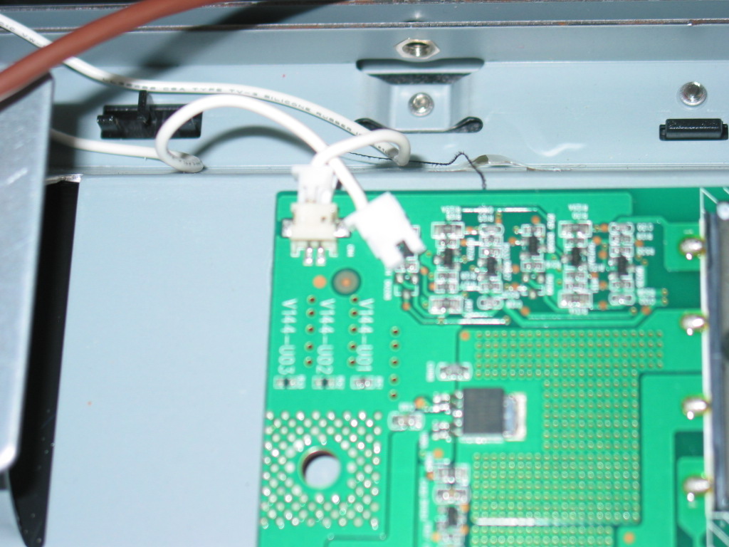
This is an easy problem if you use good cutters. Just cut in half all connectors, including the one for the common ground which is at the corner of the board:


It's really as simple as that!

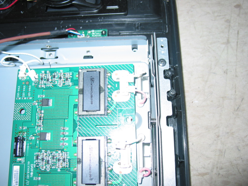
The next problem you'll encounter is that the new board is slightly larger than the original and doesn't fit the borders made by the little metal plates at the two ends.
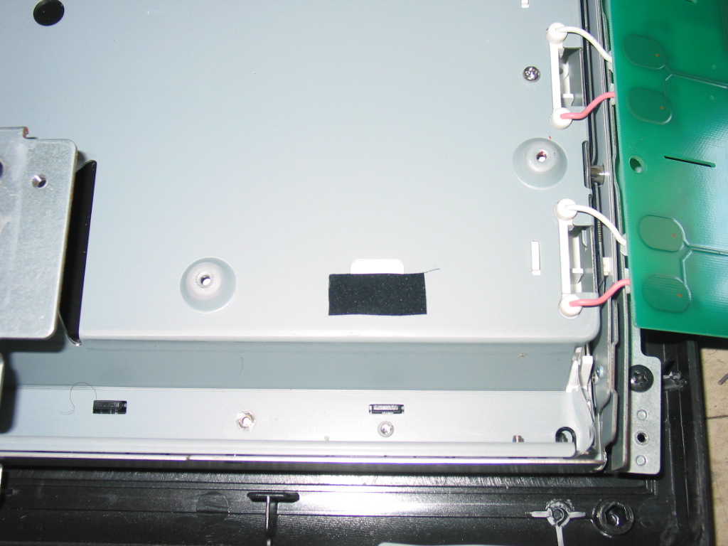
I just bent those a few times until they broke and then put tape on top to make sure they won't short:

The great news is the main cable doesn't require any changes at all, it just goes straight in:

Next, of course, you'll need to tweak a bit the metal shield (if you opt to install it at all) so that it can do some decent covering and allows for fastening with bolts. A little tweaking with pliers goes a long way:

Finally, you won't be able to use most of the fastening bolts, but you should be able to use at least three, which is more than sufficient for steady positioning.

I didn't take a picture of the working TV since it sold and went out before I could make that extra shot.

And if you wonder how did I know all that in the first place...well, that's just how I am.

Modesty comes first, of course.

Monday, August 22, 2011

Dell W5001C power issues, sound without picture problem and some other thoughts

Below is a request from a potential customer and my response to it.

This time it is not the usual customer complains, I promise.

The email, I take it, points to an earlier post in this blog, where the issue is also mentioned...but I figured I'd post the question and the answer anyway.

After all other professionals deserve to know what we think about them...and maybe even that we tend to sometimes admit we might be wrong...

Question:  How much to send in what ever boards for you guys to fix?  I turn the power on, and it takes 3...4...5  8 mins for it to boot up.  Then the tv is fine for hours and hours.

The Caps look good, but like you said maybe they are out.  I read a few ppl that posted after they did the fix you told them they get no picture now but sound and high pitch sound.

So how much and what are the odds you can fix my issues.

Thanks,

Another DELL Suckka

Kevin

Answer:
First off, Dell has very little to do with all this.

Like most American brands these days it's just a hat over an Asian company. In this case - Samsung.

The few ppl who have picture but no sound have a completely different problem (probably this one), which is the actually the even more common issue with those TVs and is more expensive to fix too; it is completely unrelated to the delayed power on.

What you describe sounds 100% like bad capacitors. It may be the ones from the post, it may be different ones...it may even be capacitors not on the power board, but on the main board...because there are ones in both places and they actually even do the same things...so there's always chance that it may be the other ones that have gone bad...and there are quite a few of them too.

But, statistically speaking, you can't go wrong starting with the ones the article talks about.

I know that's what I'd do before investigating anything else.

Working in TV repair industry for a while made me rethink my opinion of doctors who tell you bunch of seemingly useless stuff to do whenever they see you.

I mean if you see 50:1 ratio of problems with certain syndromes it is only natural - a sign of intelligence, in fact - to expect that the every new case with such symptoms will carry the same cause and therefore be treated the same way...especially if there's no big hurt doing it anyway.

Seriously, doctors are maybe not such a morons after all :-)

Tuesday, June 7, 2011

Proview 3200 / RX-326 does not power on / shuts off / 200-100-HX276 problems

The Proview 3200 / Proview RX-326 is rather old and if you go through all the pain to actually disassemble it it may be worth to read this article to find if you can save a buck or two by repairing the power board and the main board by yourself rather than spending just south of $100 for a replacement of each.

These are the typical problems I am seeing with those TVs:

1) Completely dead TV - no front LED, nothing - suggests bad power board 02144-B306.
See this article for how to test it (note it's slightly different as its normal output is 12V and not 24V!) and if you need it repaired check the Coppell TV Repair online store.

2) TV comes on, but there's no display back-light. You may be able to see display changes with a flashlight or at the sun, but no back-light - that's either bad inverter or , very often, again bad power board.
See the links in the above case scenario for how to test the power board and send it for repair if you have to.

3) TV's standby light comes on, but when powered it either flashes green for a moment and then switches back to standby orange (or red) or switches to green, but display remains dark and you can't switch it back to standby color by pressing power, or display flashes for a second and then TV turns off, or sometimes it may turn on and stay on, but next time you try to turn it on it won't move...or any combination of the above.

This article is actually about that case...it's not only power board repair infomercial :-)

But, while at it, first and foremost again check the power board and make sure it produces reliable 12V on the primary as explained in our article.

If that's good then the problem is most likely on the main board 200-100-HX276 .

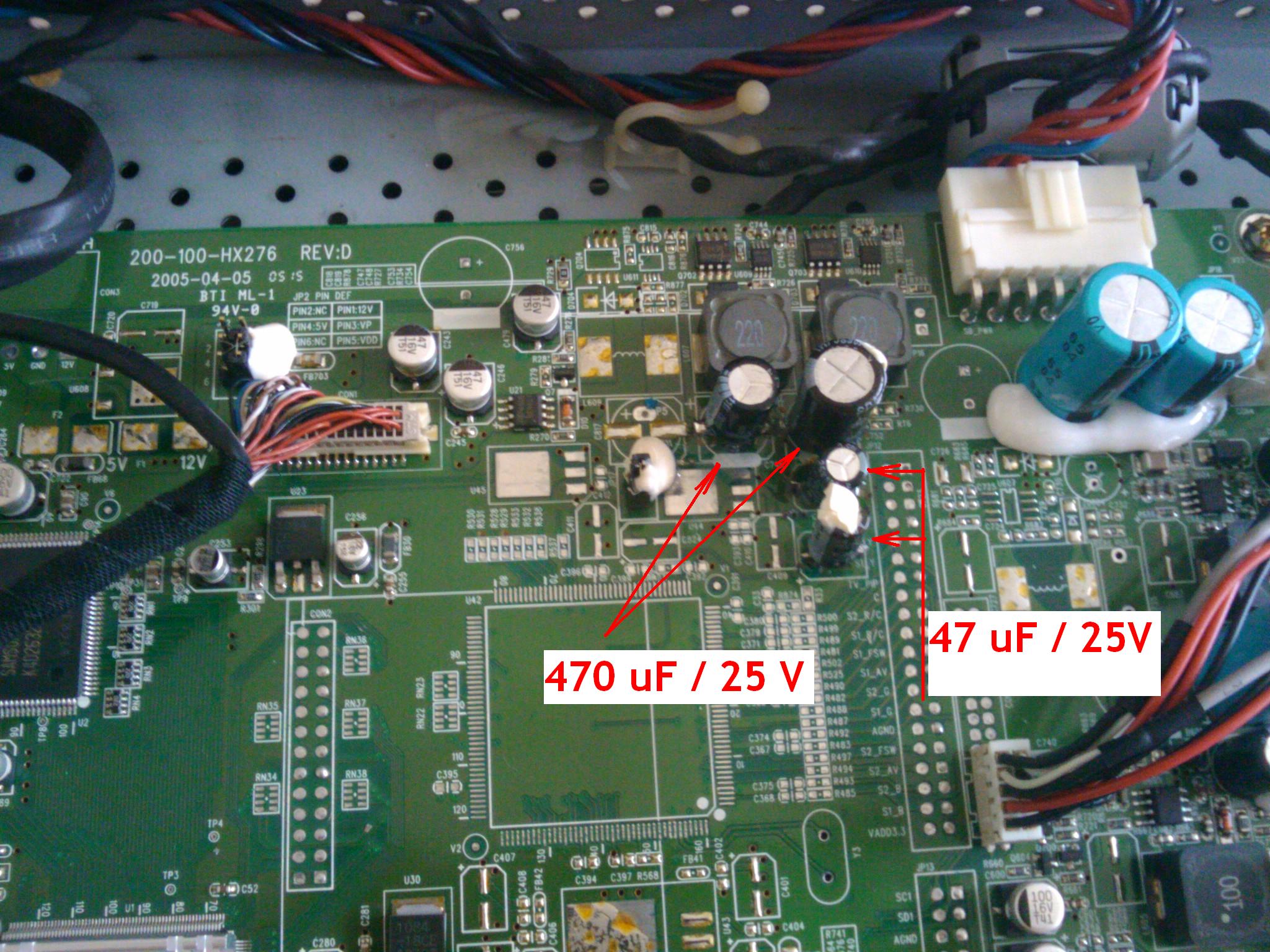
To make the long story short here's a picture of what you need to replace:


This picture was taken after the replacement was done.

The original capacitors were aluminum ones and did not show any signs of malfunctioning visible to the naked eye.

As you can see we've used standard replacements and not aluminum ones. In fact on this picture one of the larger ones is 680 uF. Don't ask - we just did it.

If you need the capacitors, drop us a note and we'll add a link for purchasing the four at a reasonable price. But the post here is with the main idea to share the know-how , not to benefit from selling the kit.


The replacement itself is not a rocket science, but is somewhat delicate partially due to the tight space.

Still way better than having to pay $90 plus shipping for a replacement board!

Wednesday, April 6, 2011

How to test STK795-518 YSUS IPM for defects

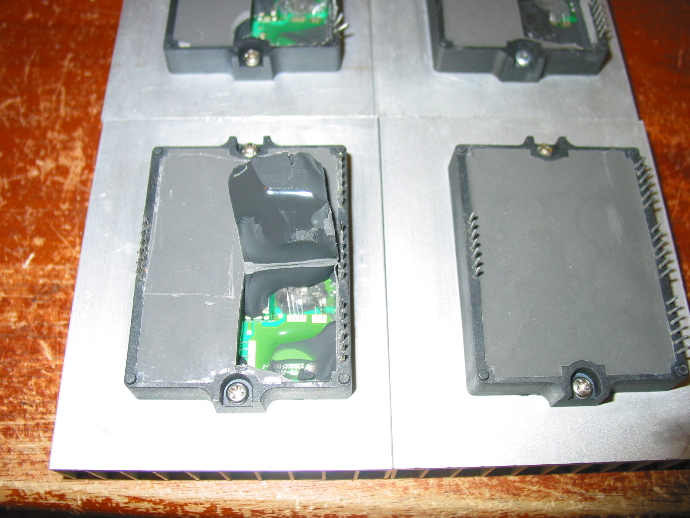
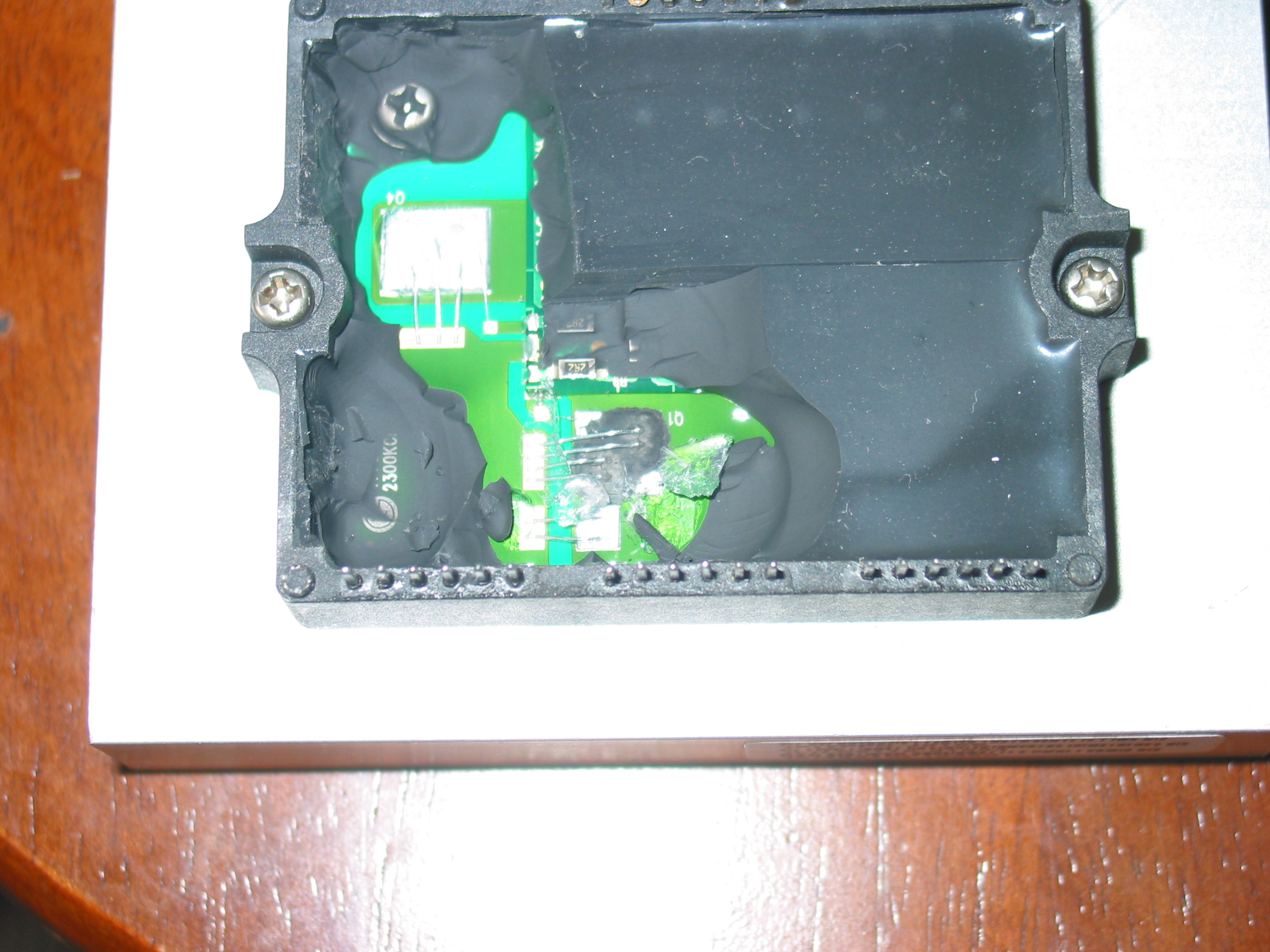
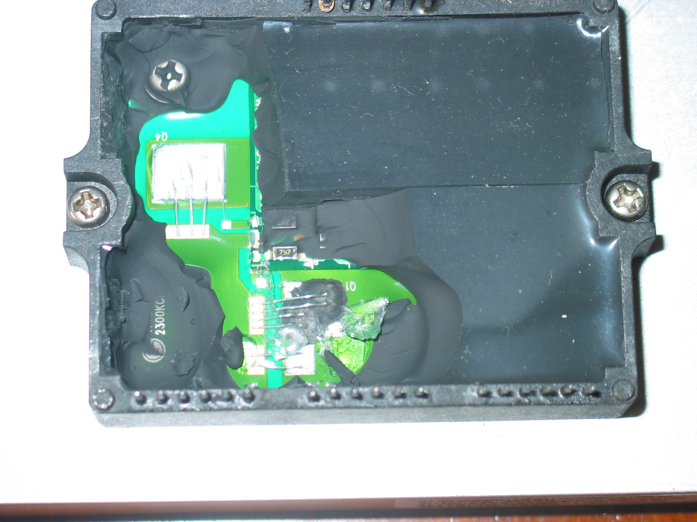
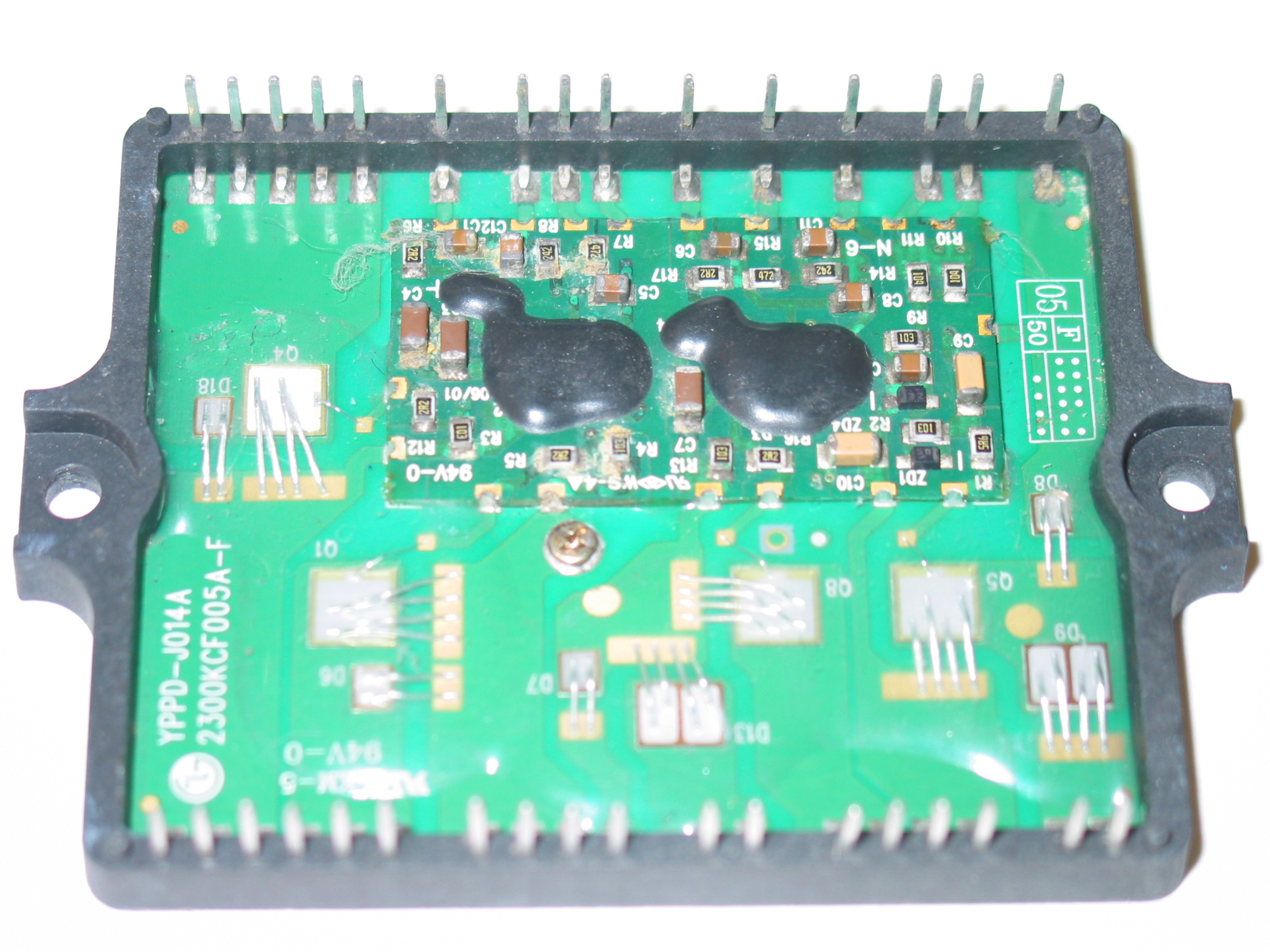
This article will tell you a few quick checks for the most common failures found in Sanyo's STK795-518 used  in YSUS board LJ92-01200A and a 50'' plasma sustain board (let me know the number if you have it!).

We at Coppell TV Repair do our best to protect ourselves and our customers from bad parts, but ultimately nobody would take care of the customer than the customer himself.
Of course by publishing such information we inevitably also continue to indicate our competitors some of which we are proud to see as subscribed followers of our blog.

For what it's worth, that's the nature of this business.

Competitors, feel free to copy this and post it on your sites...you are going to do it anyway, you might as well do it with our blessing.

Now back to the task at hand.

The tests described below are applicable with the IC on and off board. Of course we strongly recommend that you apply them before you solder any IC on the board - you'll save time and you'll also increase the odds of being able to return the IC back to the vendor with least worries.

Those tests are not complete in a sense that they do not guarantee that the IC will work properly.

But they clearly indicate if it is bad and while it's not guaranteed, we find that 99.9% of the time when an IC passes them it works good on a board.

It all boils down to detecting continuity (shorts) or low resistance (ohms) between certain pairs of pins on the module..

If you find one the STK795-518 is certainly bad.

The tests can be done with the IPM on or off the board.

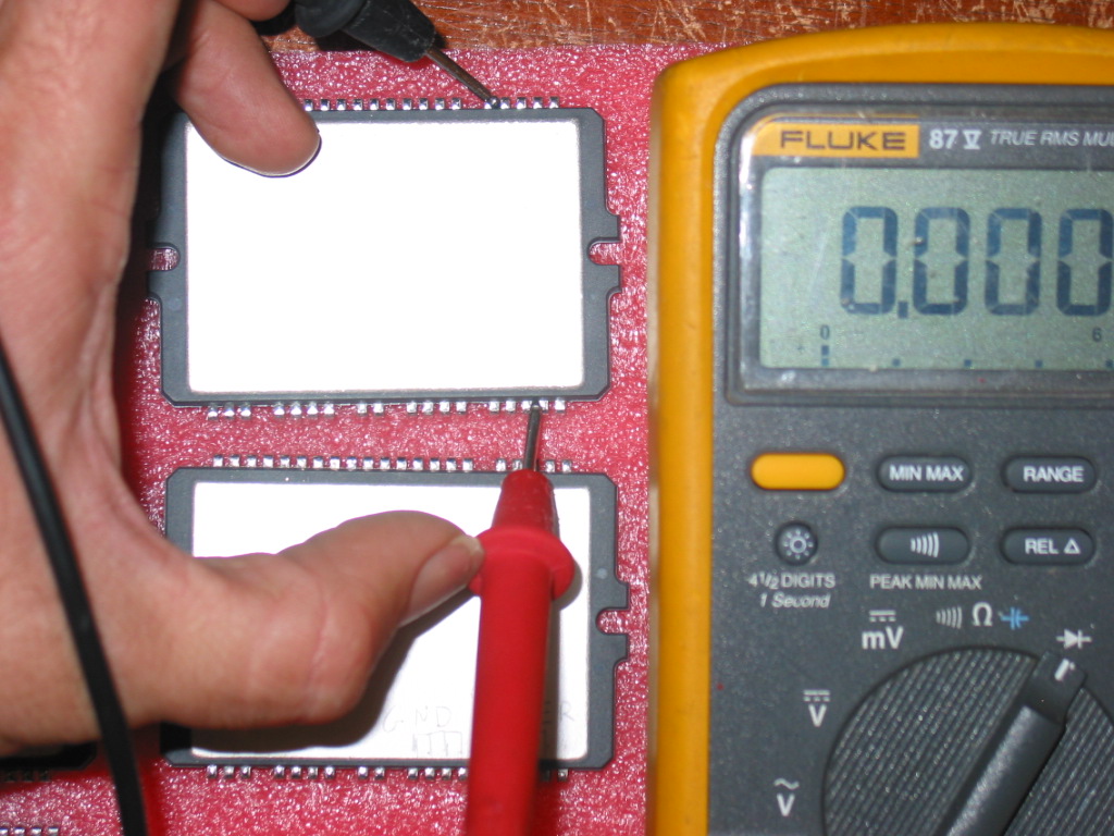
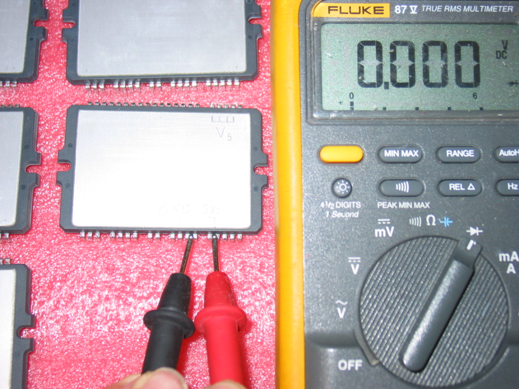
Here's a picture of the pins of interest:


As you can see there are 4 points of interest - GND (Ground), Vs (supply power), SUS and ER, which are the two outputs for the sustain and energy recovery accordingly. Those two are shorted on the board, but on an actual IC are NOT connected to each other.

Here's the simple rule:

THERE MUST BE NO CONTINUITY (SHORT) BETWEEN ANY COMBINATION OF THOSE!

IF YOU FIND A SHORT THEN YOUR STK795-518 IS DEFECTIVE.

This is actually 100% correct for all other plasma IPM modules.

There are 4 inputs/outputs which result in 6 possible tests (Vs-GND, Vs-SUSout, Vs-ERout, GND-SUSout, GND-ERout, SUSout-ERout), but in reality two are the most common failures that we see in STK795-518:


1) Vs shorted to one of the two sustain outputs:

2) The other sustain output shorted to ground:

Saturday, February 26, 2011

MLT168A power for ILO LCT27HA36 , AKAI LCT2785TA - how to test and more

MGMEET MLT168A is very similar to MLT166A about which I had blogged before.

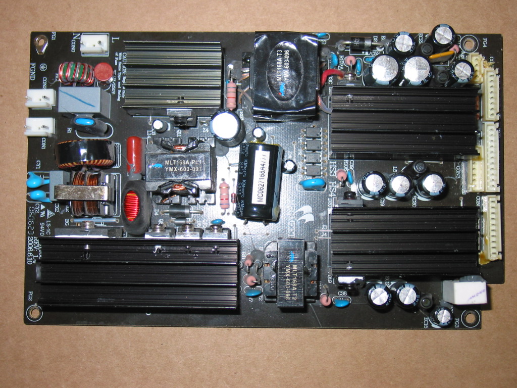
Here is how it looks from the top:


The power input is the single one at the upper left corner, just below the top edge of the board. Its pins are marked with N and L.

All the outputs are on the right side of the board.

When AC is connected to the board there is a single 5V output and it is on the connector marked CON3.

Those 5V are called standby voltage and are used to tell the power board, through another pin on CON3 to wake up and generate all other voltages needed for the normal TV operation.

Using a voltmeter you can check if you have 5V on the appropriate pins on CON3 as per the following illustration (click to see full image):


So, once again, when power board is supplied AC the only output voltage that should be there is the +5V standby voltage. Using a voltmeter you should be able to measure 5V between either of the two pins as displayed above and the ground (which is any of the Ground pins or the TV chassis).

To turn on the rest of the voltages you need to pass the +5V from the standby to the POWER_ON pin.

If there's a cable plugged in in CON3 you can use a wire to short those two. It's OK to short +5V directly there for reasons we will see in a minute.

We didn't have a good connector so we turned the board and soldered a short wire between those two.

Here is how the back of the board looks where the output connectors are:
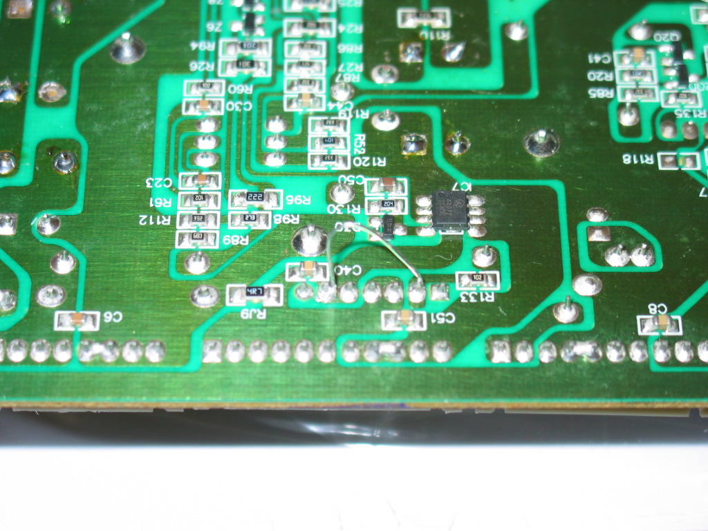
And here is what it looks like when we passed the +5V to the POWER_ON pin:

While usually it is not recommended to pass +5V directly to anything (just out of precaution) in this case it is easy to see that there is a resistor (R133) at the input of the POWER_ON line. This means it is completely safe to pass +5V directly there.

Once you have signaled (turned on) the power board you should be able to measure all other voltages as indicated at the top side of the board near the connectors - +12V, +9V and +24V.

Note they may be slightly off the printed values. If you get 11V instead of 12V that's OK as long as it is stable.

If it fluctuates or if it is off by more than 10% you've got a problem.

And if you've got a problem you know who to call.

No, AFTER the ghost busters!

Friday, January 7, 2011

Samsung 214T LS21BRBAB does not power / blinks once

This is a story about pragmatism. A tiny bit of knowledge sneaks it at some point, but for the most part it's just a story. If you expect ground breaking discoveries, mysterious occurrences or erotic adventures then you should move to some of the next posts. You may have better chances there. Bear in mind I am not promising anything.

A local customer called on the phone and asked if we can fix 21'' LCD monitor.

We told him it's probably cheaper to buy a new one these days, but he said he's curious what could it be and is ready to pay our minimal service fee for 32'' LCD TVs for us to take a look.

Monitor was 21'' Samsung 214T [R] S, model code LS21BRBAB/XAA and as customer told us he had looked it up on Google and, upon finding a common failure in the power board caused by bad capacitors, has replaced them to no success. So he wanted us to take a look and even if we can't fix it he'd pay us $55.

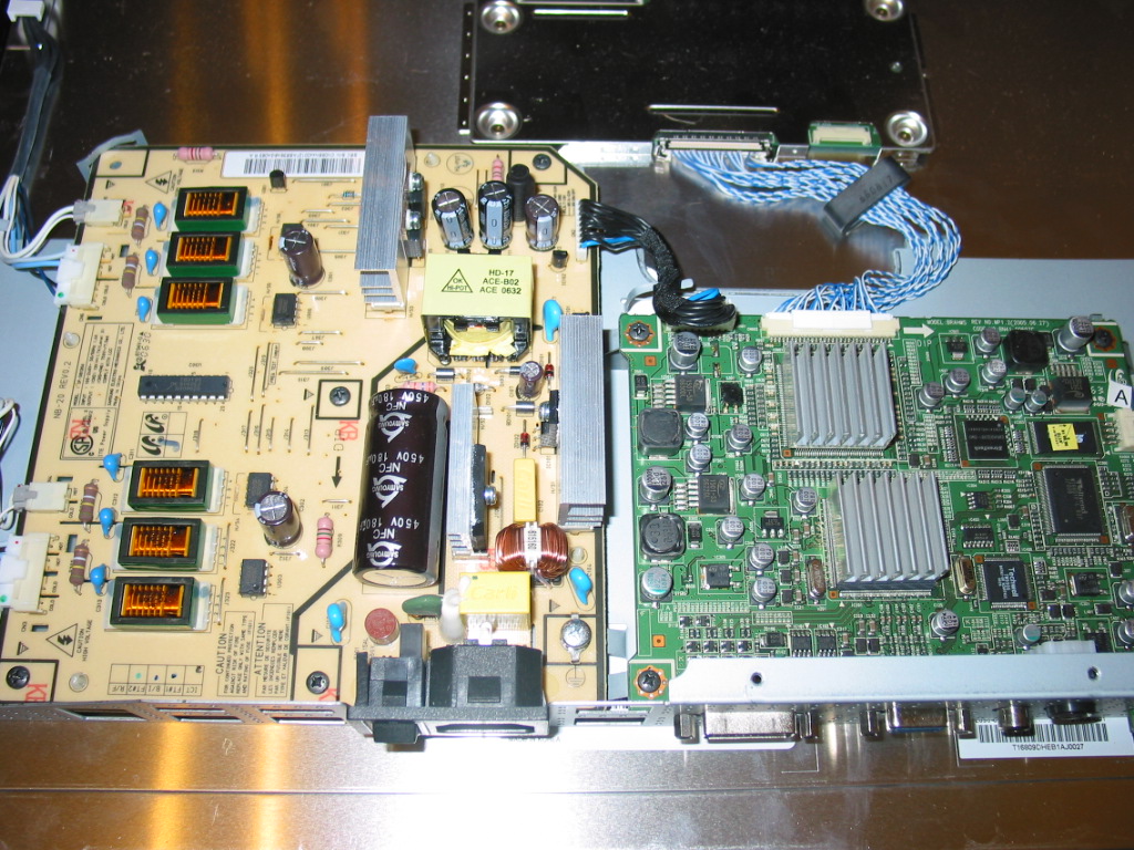
For your viewing pleasure, this is how Samsung 214T looks inside:


For the technically challenged and the rest from the normal side of the humanity the brighter thing on the left is a power board and the green thing on the right is the main board.

The power board incorporates in it functionality for providing the special needs of the florescent lamps that provide backlight for the LCD assembly.

Well long story short, the customer has replaced all caps on board and, from the look of it, has done it well.

The monitor was powering on all right, then the display would flash for a split second and instantly turn back again. Monitor would power on and off, just wouldn't stay bright.

Many LCD TVs have the same symptom and the cause us, overwhelmingly, in the circuits that provide power to the back light lamps. In large TVs they are often on a separate board, but smaller TVs and monitors they are sometimes incorporated in the main board just as shown here.

There are several reasons why something like that would happen and before troubleshooting it I took a quick peek at the power board. I was looking for a board label, something that would allow me to look it up on eBay and see what would it cost.
What I had come across was a label NB-20 towards the top of the board.

So I looked that up and a single result showed up offering me a "TESTED, WORKING POWER SUPPLY BOARD NB-20". It was asking $69.95 plus $9.95 shipping. Here's the actual link.(bear in mind it may be invalid by the time you read this).

$80 is a lot of money for a 21'' LCD TV. Way too much in my book.

But then again the link mentions that this is board "IP-58130A", so I searched for that.

Bingo! $26.99 direct from China, 20,000 sales seller, 98.8% feedback.

Reserved as I am , I think this is a no brainer.

I put together the TV as quick as possible and plan on telling the customer to pay me our standard fee less $27 and get a new board from there.

It's not about the money...and I know I can fix the damn board.

I just don't think I can do it the first time for under $27.

Friday, December 10, 2010

If you consider buying parts from China consider this

Next time a customer complains that they received some of our ICs with bent legs I swear I'll send them here to
see some of the REAL problems when purchasing parts.

All of the below are sold to as for "new" and, if you can believe it, prices are as for "new".

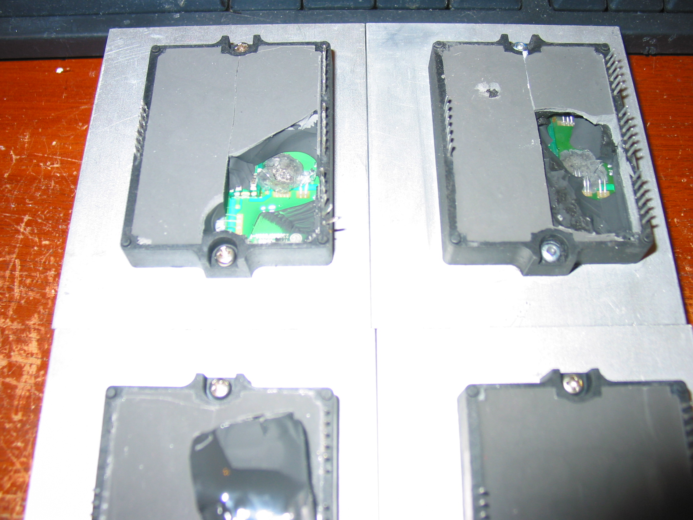
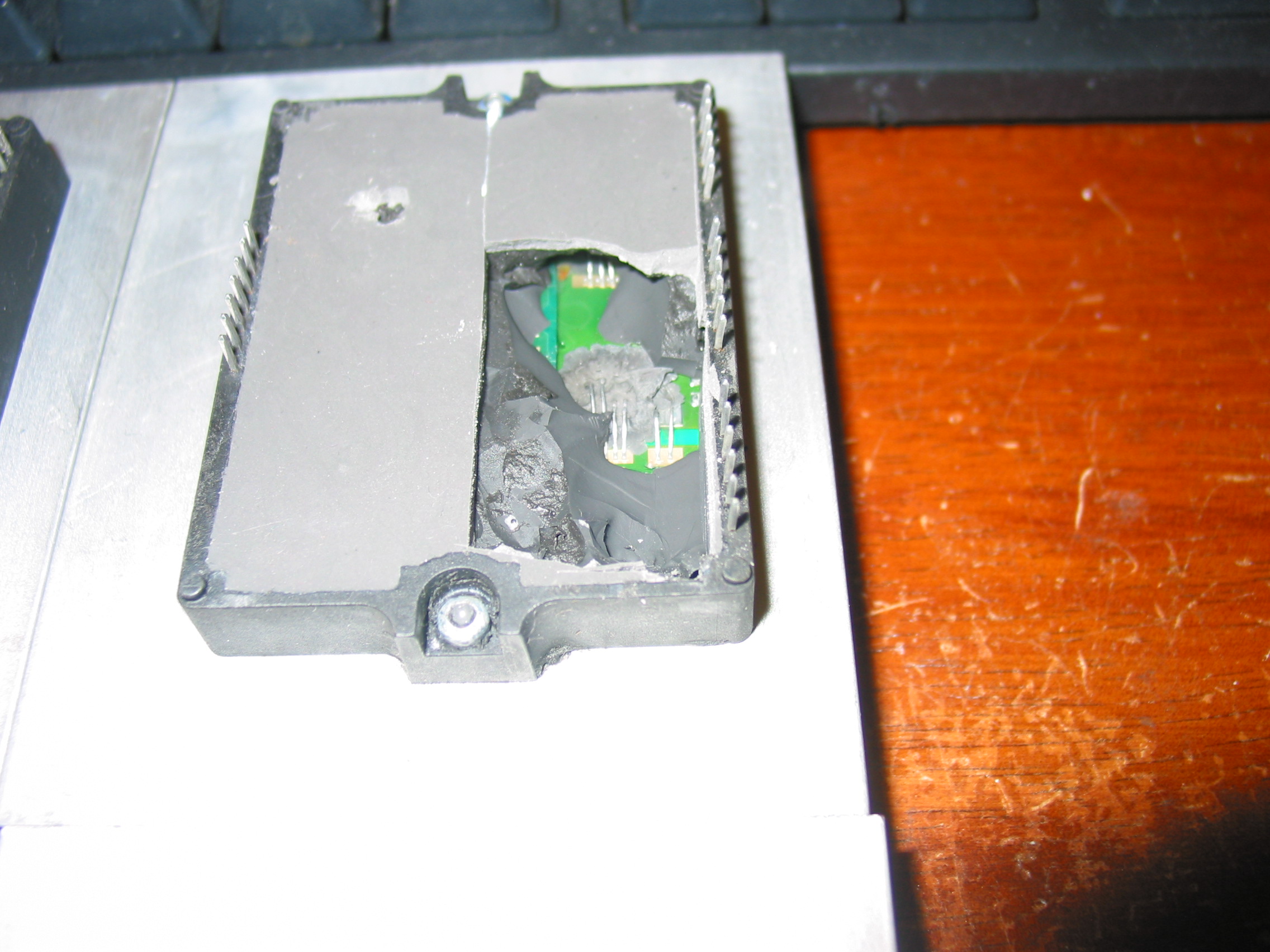
After 2 didn't work right out of the box we took the freed to cut them open and then picked another two from the same box and opened them WITHOUT INSTALLING AND TRYING THEM FIRST.

I guess it is not hard to predict what the fourth IC on the image below will look like inside, is it?


Rust on ESD components, rust on pin solder connections...

Notice how the original black filling of the IC is covered with a thin layer of a gray one.


There are several take home lessons from this:

1) Buying from China is risky. And it's not because your Chinese partner necessarily wants to trick you. Those parts were received from a company we've been working with for some time with and we do not doubt their honesty.
The problem is they themselves aren't good enough to filter the bad parts that they purchase.
And because we've tried several different vendors we can say this is the common situation out there.

2) It pays for a customer to purchase parts from a company that actually uses them in its own work. If we had sold those parts to customers and we haven't had to use them ourselves we'd probably be doubting our own customers' honesty when they call back and say that apparently brand new working parts do not work.
But since we use them ourselves we act as a first line of quality assurance for customers.
When the product you're buying is not only valuable, but greatly affects the time you spend on a job it does matter to know you're getting quality stuff.

3) Next time you want to save a penny - or even a dollar - by buying directly from China consider all the headaches that a local American company saves you. Not to say all American companies are perfectly well equipped to know the difference between good and bad parts...not at all.
But it's it's still a whole lot easier to hold a company responsible in America than in China.
And frankly, if there was an American company that could offer us the parts we need at decent prices we'd sure be buying them from here!

Thursday, December 9, 2010

MLT166A POWER BOARD TEST AND REPAIR - AKAI LCT2701AD and LCT2701TD

A company has sent us a bunch of those boards to repair and we are sharing some of our expertise on how to test and repair them.

Those supplies are used in AKAI LCT2701AD and AKAI LCT2701TD models.


(If you need Coppell TV Repair to repair your power board please first make sure it needs repair as per the below instructions and then contact us to arrange repair. From what we learned odds are good it may indeed be faulty.)


Indeed, this is apparently a poorly made power board because all of the ones that we received had been previously serviced already.

So how do you know if it works?

TESTING POWER BOARD MLT166A
When connected to 110V AC through the main connector CON0 (at the lower right corner on the picture) the board is only supposed to produce 5V standby voltage. This shows up on connector CON2 which is the second white connector from the top on the left side of the board. It is between the two heat sinks and next to the order of three capacitors EC18, EC19 and EC20.

When testing the board we recommend that you disconnect all load from it, i.e. unplug all connectors except the one that feeds AC power in.

The CON2 connector has 6 pins organized in three groups of two pins like this (starting from the top):

* STB (aka PS_ON)
* STB
* GND
* GND
* +5V STB
* +5V STB

The lowest two pins is where you get the standby 5V power. You will need a digital multimeter to measure them. It is OK if reading is 10% off, i. e. anything between 4.5 and 5.5 V will do as long as it is stable.
To measure the voltage you connect one probe to either of the +5V STB pins and the other to either of the GND pins.

To activate the power supply (which is what happens when you pres the POWER ON button on your TV) you need to pass the 5V to any of the two STB pins.
We do that by simply soldering a resistor of about 100 Ohm between the two opposite pins of CON2, but you can as well just short them - in this particular case.

Once you do, the board should start making a humming noise and the rest of the voltages should show up:

CON1 has 3 sections - 3 pins for +12V, 3 pins for GROUND and the rest for +5V:
* +12V
* +12V
* +12V
* GND
* GND
* GND
* +5V
....

CON3 and CON4 each have half of their pins for GND and other half for +24V needed for the inverter boards.

If you get all those voltages then your power board does not need a serious servicing.

COMMON PROBLEMS WITH MLT166A

1) Probably the single most common problem with those boards are bad electrolytic capacitors. You should check and replace those regardless of whether the above test passes or fails. Bad capacitors can change board's behavior under load and can render it useless even if it passes the simple no-load test.


Electrolytic capacitors are the cylinders with shiny tops that can be seen all over the board.

Bad ones can usually be spotted by their bulged tops compared to the other, normally flat ones.


Behind the above mentioned connector CN2, for example, is a trio of capacitors that had to be replaced (or was already replaced) on any single board that we've seen. Those are EC18, EC19 and EC20.
Originally they are rated 1000 uF / 10V each.
If you need to replace them, you should replace them with 105 degrees , 1000 uF or slightly more and at least 10V rated capacitors - the higher voltage, the better (bear in mind they get larger though).

Since EC18 and EC19 work in parallel it is also completely acceptable to replace both of them with a single 2200 uF / 25V capacitor that will work better and last longer.

One one of the boards we serviced we've also had EC11 apparently bulged so we had to replace it as well.

On your board you may have yet a different one that needs to be replaced.

If you need parts, let us know and we can sell and send them to you!

2) The 5V output on CN1 (the lowest 5 pins of the connector) provides power to all the logic functions needed when the TV is working. They flow through a power transistor located at the back of the board which carries both filter and control function.

Simply said, think of it as an operating switch which has 3 connectors - input, output and a controlling (gate) connector which tells it when to activate.

That transistor is apparently badly rated because on many of the boards we received it was bypassed by simply shorting the input and output and completely ignoring the switch control input:


While rude, this solution is a cheap and efficient one if you don't see the 5V at the connector of your board , but you see them on CN2.

If both of those fail to help you, we'll be glad to try our luck diagnosing and fixing your board for $50 or so.
Just send it over!

Wednesday, April 14, 2010

How to find plasma display panel (PDP) voltage settings - ZBias, Va, Vs, V set_up etc.

Homebrew technicians and even professional technicians with lots of experience with CRT TVs, but not familiar with plasma TVs often ask me how to find the ZBias or Va or Vs voltage for the plasma they are working on.

It usually happens when they send us a Z sustain board or Y sustain board for service / exchange and we send it back with a note remidning them to adjust ZBias after the board arrives.

Everything in a plasma TV revolves around the display and plasma displays, much like computer processors, may come in with slightly different parameters, even though they'd still carry the same panel information.

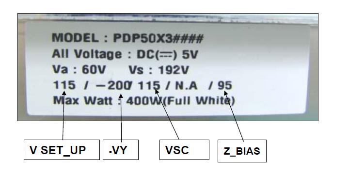
So all plasma TVs , in fact all plasma panels, would have a sticker somewhere on the back of the panel , usually in the upper right corner, which indicates the data for this particular panel.

It looks like this:
(the picture is courtesy to LG electronics, one of the largest plasma panel manufactures in the world. Did you know that brands like Philips, Insignia, Vizio, Magnavox are using either LG or Philips in their plasma TV products? Yes, the core of the TV is made by very few big name PDP manufacturers!)

Hope this helps!

Monday, April 5, 2010

The Polaroid / Memorex mess 200-107-GT32XA-AH, 200-107-GT32XA-BH, 200-107-PF261XA-CH and more

In March I blogged on the ability to interchange main board between Polaroid TDA-03211C and Polaroid TDX-03211C.

A few days ago I had a customer bring in a Memorex MLT3221, which, deisgn wise, appeared the same as the above mentioned Polaroid models. It was apparently the same piece of equipment just branded to a different company.

Well, almost the same.

Even though it is the faulty power boards that those Polaroids are notorious for, the Memorex MLT3221 had an apparently good power board - first because it had all the produced voltages neatly printed on the board and second because they all checked.

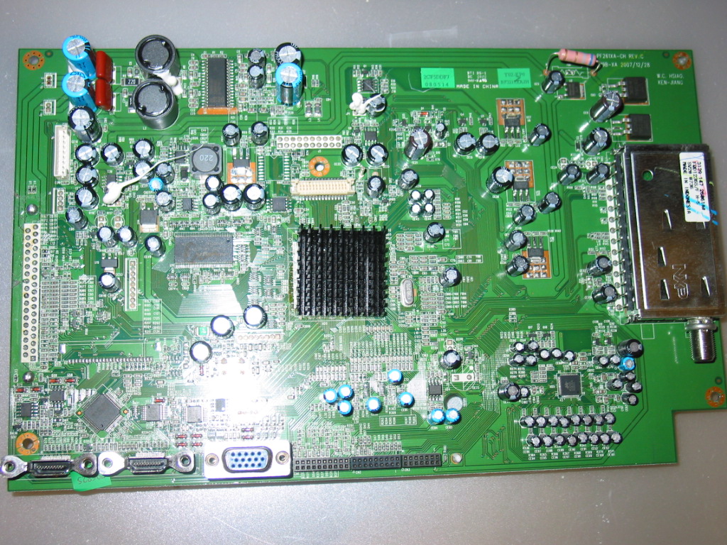
So apparently it was (again) the main board. 200-107-PF261XA-CH.
Presented here for your viewing pleasure:

Well, it turns out this boad is rare. Especially if you search for a board for Memorex.
In fact, I did not find any availability for Memorex.

However, I did find a board with the same tag available for Polaroid TDX-03211C.
You guessed it, it worked.

But wait, it's even more interesting! Suppose you do not find 200-107-PF261XA-CH for neither Polaroid nor Memorex. What do you do then, throw the TV out? Pay $150 for a main board for a 32'' TV when you can get a new one on Craigslist for $250 and at Walmart for $300?

No, you can simply use 200-107-GT32XA-BH from Polaroid TDX03211C and therefore, because of my earlier post, you can also use 200-107-GT32XA-AH from Polaroid TDA03211C!

And I am not kidding you, it works! I tried :-)

There might be the minor issue of having to see "Polaroid" instead of "Memorex", but if you find the board at a good price that would hardly matter a lot, right?

And finally, if you use Polaroid board in Memorex you will need a little extra work to extend the antenna cable connecting the board with the external antenna outlet.
You see, the Polaroid boards have the antenna receiver placed higher on the board and turned horizontally as can be seen here:


All in all, though, none of these is a deal breaker.

I hope you can use that information and it can serve you well as it did serve me!

And do not forget to order your parts and services from http://www.coppelltvrepair.com/ :-)

Friday, March 26, 2010

How to identify burned buffer boards LJ92-01203A LJ41-02761A LJ92-01202A LJ41-02760A

(UPDATE 25 Oct 2010  - I have added another article with additional details on the subject. Find it here.)
(UPDATE Dec 2012 - now the Y-Main and a set of brand new, Samsung OEM buffers is available at our store.)
(UPDATE Feb 2013 - our store now has listings for both the upper buffer LJ92-01202A and lower buffer LJ92-01203A - used, but tested and functional, offerred as-is; make sure you read this article and offer description before buying!)

Here's a very simple and easy method of identifying burned buffer boards LJ92-01203A / LJ41-02761A  and LJ92-01202A / LJ41-02760A.
Those are the buffers for Y-sustain LJ92-01200A.

The trio is used in a great number of 42'' plasma TVs using Samsung plasma display technology (the display itself and the sustain/buffer boards).

It is also famous for its common failure. The most common scenario involves burning the Y sustain which subsequently burns one or both buffers.

Now, to the point: The most common defect in those buffers manifests itself in burning and shorting the power lines and some output lines.

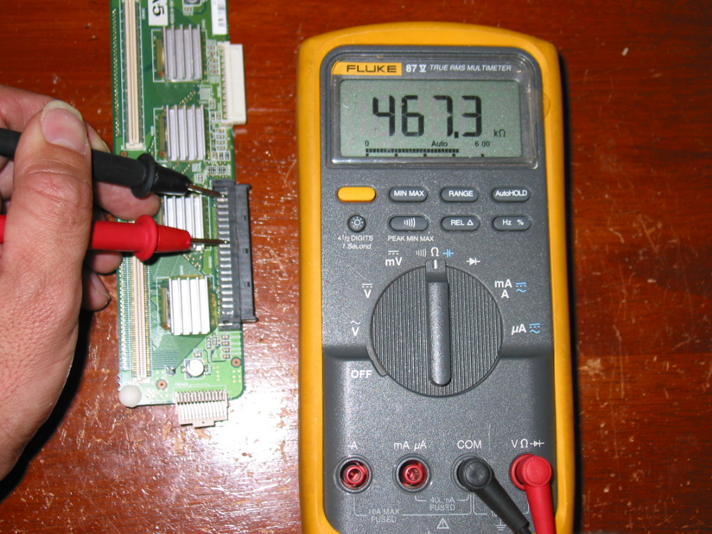
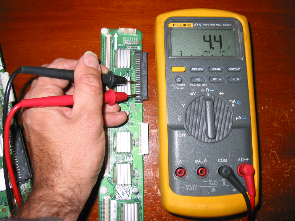
The easiest way to detect if a board was burned is to measure the resistance between its power input and ground.

Normally it should be in the range of hundreds of kOhms and when burned it is usually a matter of Ohms.

In fact, you can use the diode/audio test mode to determine if a board is burned or not.

Still , in the below examples, I am using a multimeter in a standard resistance meter mode.


On the TOP buffer board, the power lines are the top two lines of the black connector and ground are the most of the remaining connectors.

On a good board the resistance between the two may be too big in the proper direction and about 500kOhm in reverse direction.

The board on this picture is good.


On the bottom board the power lines are the bottom two lines on the black board and ground is above them.

In the example picture on the right the resistance there is only 4.4 Ohm clearly identifying this board as a burnout.

The resistance would typically be the same in both directions.

This board would prevent the TV from powering on and may also burn the Y-sustain board.

In a future post I'll also show how to identify the particular ICs on the burned board.